Modularized magnetic flux reversing motor

A magnetic flux reversal and modularization technology, applied in the direction of magnetic circuits, electrical components, electromechanical devices, etc., can solve the problems of reducing the amount of permanent magnets, high vibration and noise of the motor, and large torque ripple of the motor

Pending Publication Date: 2021-07-30
HEBEI UNIV OF TECH
View PDF16 Cites 0 Cited by
  • Summary
  • Abstract
  • Description
  • Claims
  • Application Information

AI Technical Summary

Problems solved by technology

[0003] Conventional 6-slot / 4-pole flux reversal motors can reduce fundamental frequency requirements and high-frequency related losses at high speeds, but the 6-slot / 4-pole topology has large second-order and other couplings in flux linkage and back EMF Subharmonic, which makes its torque ripple higher, resulting in greater vibration and noise of the motor during operation
The literature "Stator-Slot / Rotor-Pole PairCombinations of Flux-Reversal Permanent Magnet Machine" puts forward the principle of stator slot / rotor pole pair combination of flux-reversed permanent magnet motor, which considers the magnetization mode and flux leakage effect at the same time, but It is pointed out in the article that the back EMF waveform of the 6-slot / 4-pole flux reversal motor is seriously asymmetrical, and the torque ripple is too large, so it is not recommended to use
[0004] The Chinese patent application number 201310119939.5 discloses a surface-mounted double salient pole permanent magnet motor with a modular rotor stator. While reducing the amount of permanent magnets, the permanent magnet flux linkage of each coil of the armature winding is still bipolar. Changes, and improve the reliability of the motor, but the motor has a large torque ripple, and there is a unilateral magnetic pull on the odd-numbered pole rotor, which affects the high-speed operation of the motor

Method used


Image

  • Modularized magnetic flux reversing motor
  • Modularized magnetic flux reversing motor
  • Modularized magnetic flux reversing motor

Examples


Embodiment 1

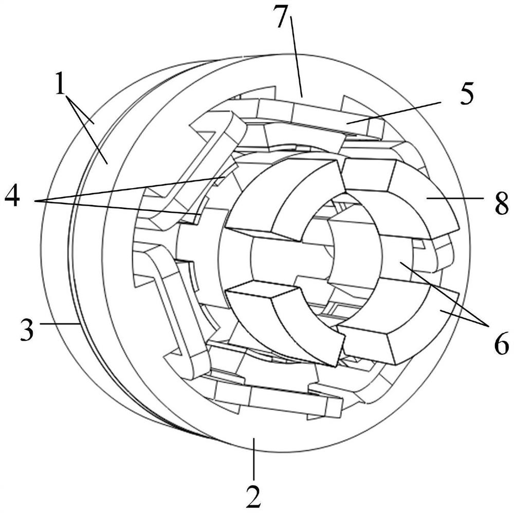
[0041] This embodiment adopts a 6-slot / 4-pole magnetic flux reversal motor with an inner rotor structure, and there are two modular units 1, such as figure 1 As shown, the effective length of the overall motor is 75mm.

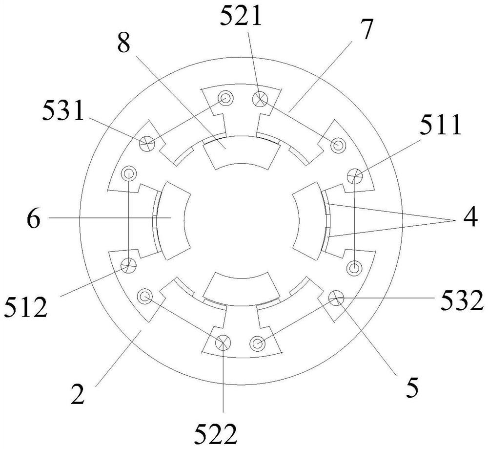
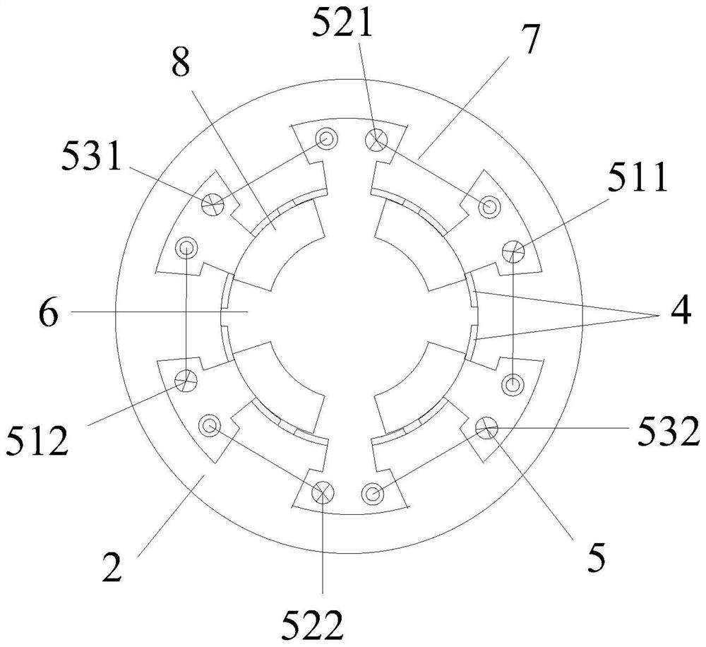
[0042] In each modular unit 1, there are 6 stator teeth 7, which adopt a salient pole structure and are evenly distributed in the circumferential direction of the stator core 2. The stator pole arc is 40.5°, the inner diameter of the stator core 2 is 70.4 mm, and the outer diameter of the stator core 2 is 128mm. The thickness of the permanent magnet magnetization direction is 1.6mm, and the pole arc of the permanent magnet is 18deg.

[0043] In each modular unit 1, the armature winding 5 has 6 centralized ring windings, which are respectively A-phase positive pole armature winding 511, A-phase negative pole armature winding 512, B-phase positive pole armature winding 521, and B-phase negative pole winding. Armature winding 522, C-phase positive pole armature...


PUM


Abstract

The invention discloses a modularized magnetic flux reverse motor which comprises a plurality of modularized units distributed in the axial direction. Each modular unit comprises a stator core and a rotor module. Through the modular design, the difference between the positioning torque waveforms of the two adjacent modular units is 180 degrees, the no-load positioning torque generated by the two modular units at the same rotor position counteracts each other, the motor positioning torque peak-to-peak value is reduced, the torque pulsation is suppressed, and the motor is more suitable for high-speed operation. Through the modular design, the no-load flux linkage amplitude of the motor is increased, meanwhile, the motor has winding complementarity and even harmonic counteracting, the sinusoidal property of the permanent magnet flux linkage of the motor is optimized, the counter potential harmonic content of the motor is reduced, and the output torque pulsation of the motor is restrained. The motor has the advantages of being high in torque density and power density and small in torque pulsation.

Description

technical field [0001] The invention belongs to the technical field of motor manufacturing, in particular to a modular magnetic flux reversal motor. Background technique [0002] The permanent magnets of the traditional Flux-Reversal Permanent Magnet Machine (FRPM) are mounted on the surface of the stator teeth, and the armature windings are wound on the stator teeth, which is easy to cool and dissipate heat. The rotor is only composed of a salient pole core, without windings or permanent magnets, with a simple structure and suitable for high-speed operation. [0003] Conventional 6-slot / 4-pole flux reversal motors can reduce fundamental frequency requirements and high-frequency related losses at high speeds, but the 6-slot / 4-pole topology has large second-order and other couplings in flux linkage and back EMF Subharmonic, which makes its torque ripple higher, resulting in greater vibration and noise of the motor during operation. The literature "Stator-Slot / Rotor-Pole Pai...

Claims


Application Information

Patent Timeline
IPC IPC(8): H02K1/14H02K3/52H02K1/17H02K1/24H02K16/00
CPCH02K1/146H02K3/522H02K1/17H02K1/24H02K16/00H02K2201/03H02K2213/03H02K2213/12Y02T10/64
Inventor 苏鹏申怡王一维李永建胡艳芳
Owner HEBEI UNIV OF TECH
Why Eureka
Try Eureka