Variable-caliber magnetic control internal spiral blood vessel robot

A robot and internal spiral technology, applied in the field of vascular robots, can solve the problems of unstable movement process, slow progress of micro-robots, insufficient power, etc., and achieve the effects of improving flexibility, increasing pressure difference, and increasing movement speed.

Active Publication Date: 2021-08-03
GUANGZHOU UNIVERSITY
View PDF9 Cites 1 Cited by
  • Summary
  • Abstract
  • Description
  • Claims
  • Application Information

AI Technical Summary

Problems solved by technology

[0005] 2. By driving the elastic bellows shell to expand and contract axially, the micro-robot is driven to creep forward. This method makes the micro-robot move forward slowly, which is likely to cause insufficient power, and the movement process is very unstable, so it cannot drive the micro-robot to do continuous movement.

Method used


Image

  • Variable-caliber magnetic control internal spiral blood vessel robot
  • Variable-caliber magnetic control internal spiral blood vessel robot
  • Variable-caliber magnetic control internal spiral blood vessel robot

Examples


Embodiment 1

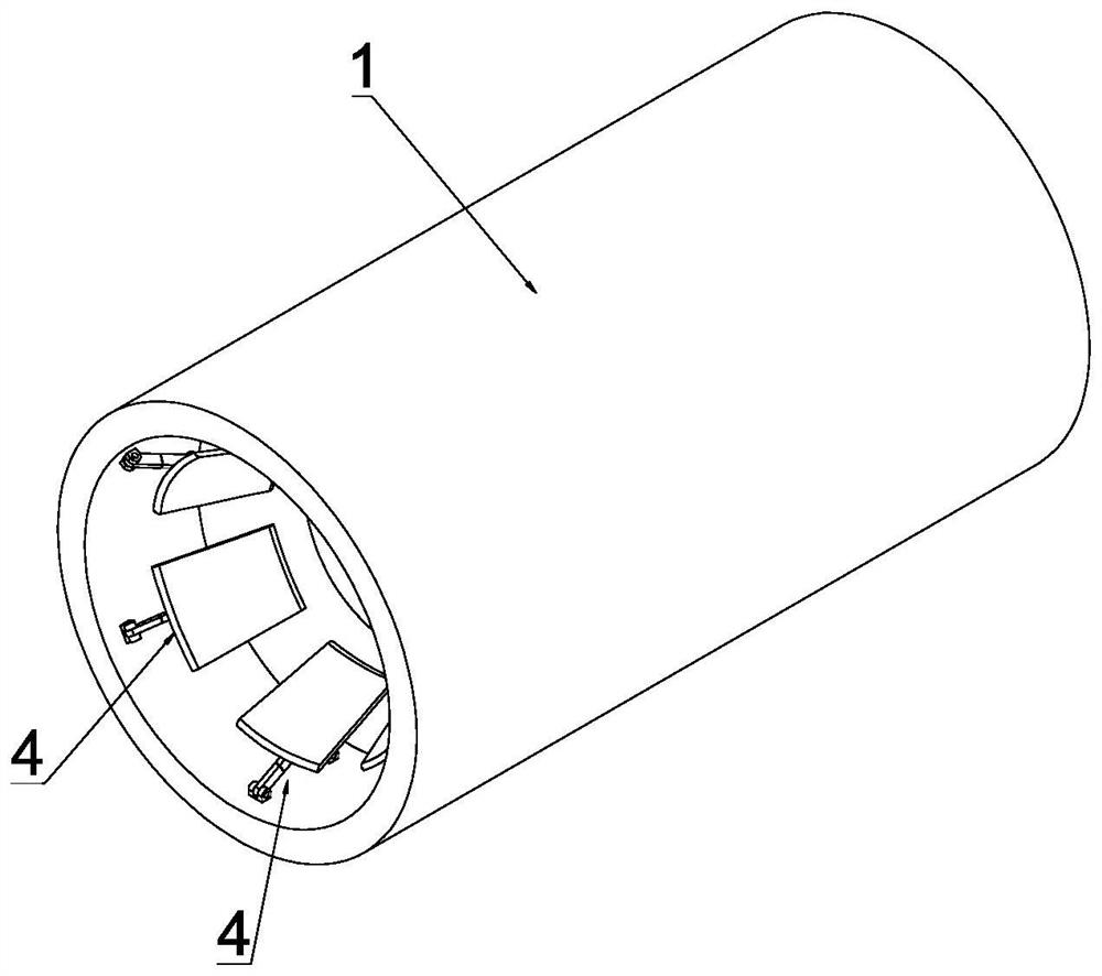
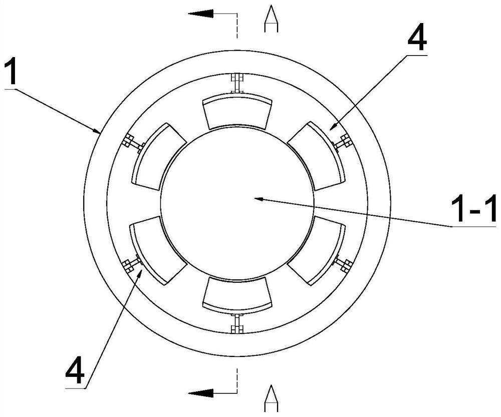
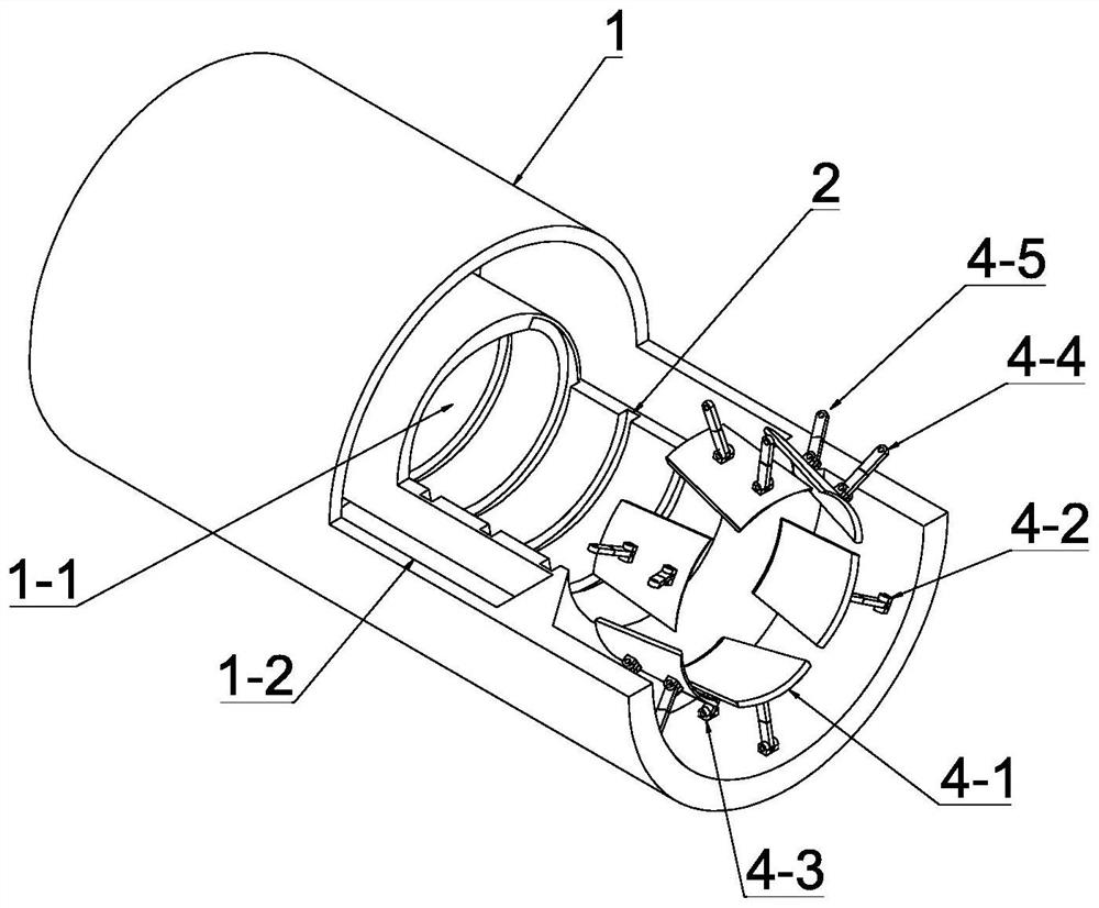
[0036] see Figure 1-Figure 5 , this embodiment discloses a variable-caliber magnetically controlled internal helical vascular robot, including a robot body 1, a permanent magnet (not shown in the figure), a magnetic field generating device (not shown in the figure), and an execution device (not shown in the figure) shown), the robot body 1 is a tubular body, and the robot body 1 has a hollow cavity 1-1 running through the robot body 1 and an annular inner cavity 1 coaxially arranged with the hollow cavity 1-1. -2, both the permanent magnet and the actuator are installed in the annular inner cavity 1-2, and the hollow cavity 1-1 includes a driving cavity 1-11 in the middle and a driving cavity 1-11 in the middle The installation cavities 1-12 at the front and rear ends, the inner wall of the drive cavity 1-11 is provided with a spiral groove 2, wherein each of the installation cavities 1-12 is fixed with an elastic annular band-shaped film 3, which The elastic annular band-sh...

Embodiment 2

[0059] see Figure 6-Figure 7 , the other specific structures in this embodiment are the same as those in Embodiment 1, except that the movable connection structure includes a hinge seat 4-6 arranged on the inner wall of the installation cavity 1-12, and the adjusting blade 4-1 is located in the One end close to the end of the hollow cavity 1-1 is hinged on the hinge seat 4-6, and the material of the adjusting blade 4-1 is a magnetic material. With the above structure, the axial magnetic field generates a magnetic moment on the adjusting blade 4-1, and under the combined action of the blood impact and the magnetic moment, the adjusting blade 4-1 swings, and the elastic annular band-shaped film 3 is continuously squeezed during the swing, so that the The diameter of the elastic annular band-shaped film 3 changes, so as to control the size of the openings at both ends of the robot body 1 .

[0060] see Figure 6-Figure 7 , one end of the adjusting blade 4-1 hinged with the hin...


PUM


Abstract

Disclosed is a magnetic control internal spiral blood vessel robot comprising a robot body and a permanent magnet, the robot body is provided with a hollow cavity and an annular inner cavity, the permanent magnet is installed in the annular inner cavity, and the hollow cavity comprises a driving cavity located in the middle and installation cavities located at the front end and the rear end of the driving cavity; a spiral groove is formed in the inner wall of the driving cavity, an elastic girdle-shaped film is arranged in each installation cavity, an adjusting control mechanism is arranged between each elastic girdle-shaped film and the inner wall of the corresponding installation cavity, and each adjusting control mechanism comprises a plurality of adjusting assemblies; each adjusting assembly comprises an adjusting blade and a movable connecting structure connected between the adjusting blade and the inner wall of each installation cavity. The blood vessel robot can advance and retreat and move in two directions, the movement mode is flexible, in addition, the movement process of the blood vessel robot is stable, the movement speed is high, and the blood vessel robot can continuously move in blood vessels.

Description

technical field [0001] The invention relates to the technical field of vascular robots, in particular to a variable-caliber magnetically controlled internal spiral vascular robot. Background technique [0002] Vascular robot is a micro-robot that can enter the blood vessel and move freely in the blood vessel. It can complete the work of removing thrombus, removing tumors, and administering drugs in the blood vessel. It is of great significance for the prevention and treatment of cardiovascular and cerebrovascular diseases. A hot spot in the field of external micro-robot research. The researchers have carried out extensive research on the vascular robot, involving the shape of the vascular robot, the way of movement, the update of the manufacturing materials, and the upgrade of the processing technology. [0003] Traditional vascular robots are generally divided into three types according to the movement mode, including swing type, spiral type and push type. The oscillating...

Claims


Application Information

Patent Timeline
Patent Type & Authority Applications(China)
IPC IPC(8): A61B34/30
CPCA61B34/30A61B2034/303
Inventor 江帆刘晨曦祝韬谢智铭
Owner GUANGZHOU UNIVERSITY
Why Eureka
Try Eureka