Jig and assembly equipment
A technology for assembling equipment and jigs, used in welding equipment, metal processing equipment, auxiliary welding equipment, etc., can solve the problem of solder joints being easily damaged, reduce the amount of interference, reduce the probability of damage, and avoid the connection relationship being damaged. the effect of destruction
- Summary
- Abstract
- Description
- Claims
- Application Information
AI Technical Summary
Problems solved by technology
Method used
Image
Examples
Embodiment approach 1
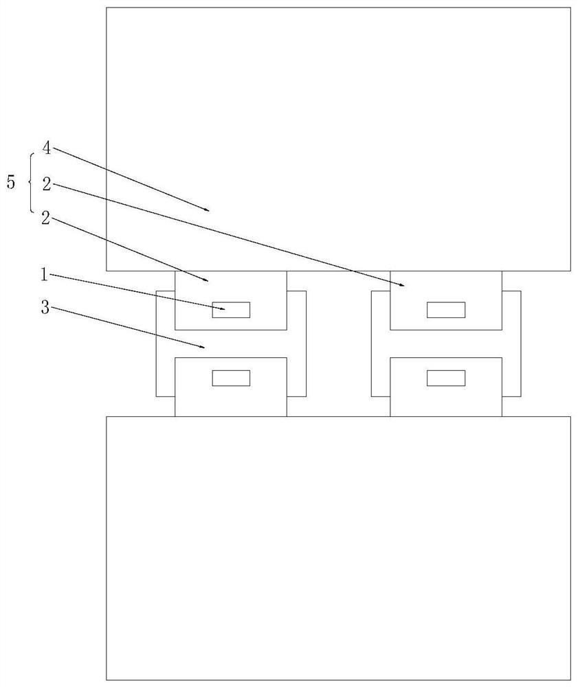
[0052] The present application provides an assembly device, which includes a jig and a handling component.
[0053] In this embodiment, the assembly equipment is used in the welding process of two single lithium batteries for transferring and positioning the protection sheet. The protective sheet is an example of the first component, and the tab of the single lithium battery is an example of the second component. The application of the assembly equipment of the present application is not limited thereto, and can also be applied in other fields. For example, in automated assembly, a sheet metal part is fixed to the body of the vehicle body with fasteners such as screws. In this example, the sheet metal part is the first component and the bodywork is the second component.
[0054] In the production process of lithium batteries, two single lithium batteries need to be connected through connecting pieces to form a battery pack.
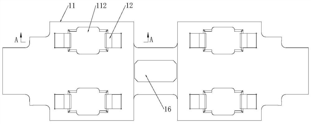
[0055] figure 1 It is a structural schematic diag...
Embodiment approach 2
[0112] Refer below Figure 13 with Figure 14 The second embodiment of the assembly equipment is introduced.
[0113] The second embodiment of the assembly equipment shows another flexible connection method between the support block 12 and the pressure plate 11 . Substantially the same parts corresponding to the first embodiment described above are assigned the same reference numerals, and description thereof will be omitted, and different parts will be described in detail.
[0114] Figure 13 is a partial cross-sectional view of the jig when the bracket 12 is in the first posture. Figure 14 is a partial cross-sectional view of the jig when the bracket 12 is in the second posture.
[0115] Such as Figure 13 with Figure 14 As shown, the platen 11 is generally flat and has an opposite top surface 113 and a first bottom surface 111 . A relief hole 112 is defined on the pressure plate 11 , and notches 114 are defined on two opposite sides of the relief hole 112 . The no...
Embodiment approach 3
[0121] Refer below Figure 15 The third embodiment of the assembly equipment is introduced.
[0122] The third embodiment is basically the same as the first embodiment, except that the third embodiment provides another installation method of the first elastic member 14 . Substantially the same parts corresponding to the first embodiment described above are assigned the same reference numerals, and description thereof will be omitted, and different parts will be described in detail.
[0123] Figure 15 It is a partial cross-sectional view of the jig when the bracket 12 is in the first posture in Embodiment 3 of the assembly equipment of the present application.
[0124] Such as Figure 15 As shown, the first elastic member 14 is connected between the pressure plate 11 and the bracket 12 . Specifically, one end of the first elastic member 14 is connected to the pressing plate 11 , and the other end is connected to the support block 12 . Both ends of the first elastic member...
PUM
 Abstract
Description
Claims
Application Information
 - R&D
- Intellectual Property
- Life Sciences
- Materials
- Tech Scout
- Unparalleled Data Quality
- Higher Quality Content
- 60% Fewer Hallucinations
Browse by: Latest US Patents, China's latest patents, Technical Efficacy Thesaurus, Application Domain, Technology Topic, Popular Technical Reports.
© 2025 PatSnap. All rights reserved.Legal|Privacy policy|Modern Slavery Act Transparency Statement|Sitemap|About US| Contact US: help@patsnap.com


