
Auxiliary equipment for concrete product mold demolding and capable of guaranteeing safe demolding

A technology for concrete products and auxiliary equipment, applied in the direction of manufacturing tools, unloading devices, etc., can solve the problems of inability to ensure the size of force, high labor intensity, and high failure rate of air pumps, so as to ensure safe demoulding work, reduce labor intensity, and improve Effect of release efficiency

Inactive Publication Date: 2021-08-03
深圳市汉工造技术有限公司
View PDF5 Cites 1 Cited by
  • Summary
  • Abstract
  • Description
  • Claims
  • Application Information

AI Technical Summary

Problems solved by technology

After the mold is brushed with release agent, manual demoulding still has the problem of difficult demoulding
The current commonly used demoulding method is to turn the test piece 180° and then use a pressurized air pump to pump air into the reserved hole at the bottom of the test mold, and pressurize to extrude the test mold. This method partially improves the work efficiency, but the air pressure is also not smooth. The test piece is extruded out of the mold, and the failure rate of the air pump is high during long-term use. Therefore, the test and inspection personnel of the ready-mixed concrete enterprise more or less need to demould by manual demoulding
The method of manually demoulding the concrete by slight impact and using inertia is labor-intensive, and the manual impact cannot ensure that the force is very easy to damage the concrete test mold, and the efficiency still needs to be improved.

Method used


Image

  • Auxiliary equipment for concrete product mold demolding and capable of guaranteeing safe demolding
  • Auxiliary equipment for concrete product mold demolding and capable of guaranteeing safe demolding
  • Auxiliary equipment for concrete product mold demolding and capable of guaranteeing safe demolding

Examples


Embodiment Construction

[0024] In order to make the purpose, technical solution and advantages of the present application clearer, the technical solution of the present application will be clearly and completely described below in conjunction with specific embodiments of the present application and corresponding drawings. Apparently, the described embodiments are only some of the embodiments of the present application, rather than all the embodiments. Based on the embodiments in this application, all other embodiments obtained by persons of ordinary skill in the art without making creative efforts belong to the scope of protection of this application.

[0025] The technical solutions provided by various embodiments of the present application will be described in detail below in conjunction with the accompanying drawings.

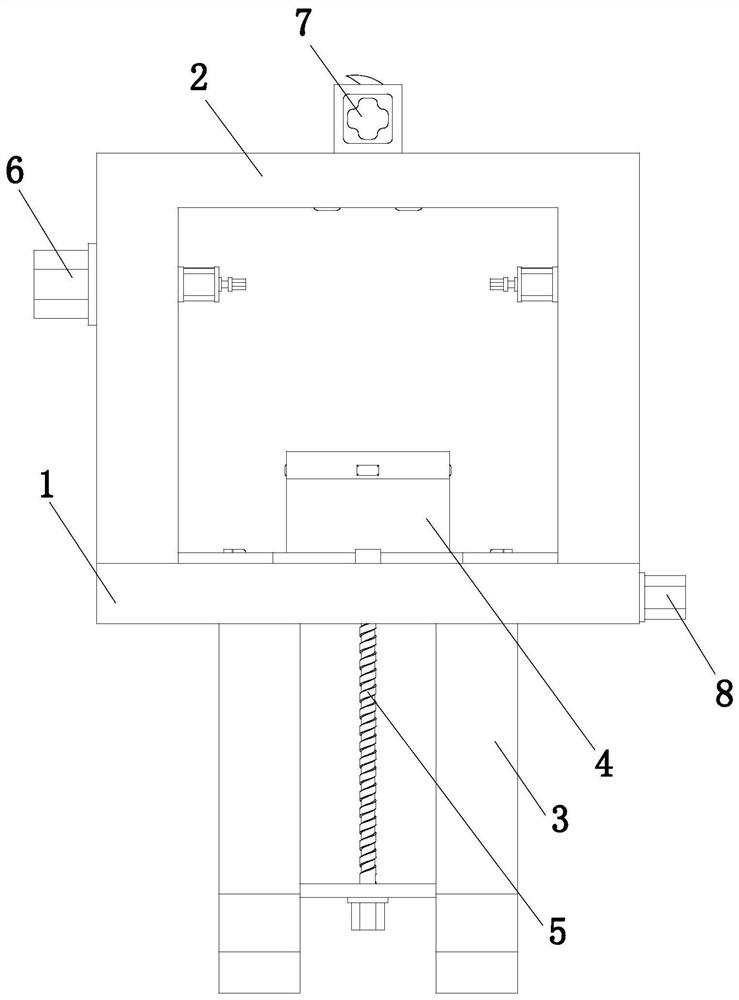
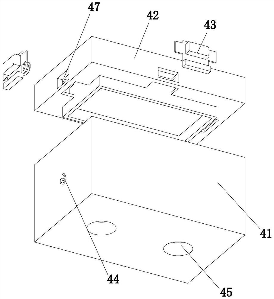
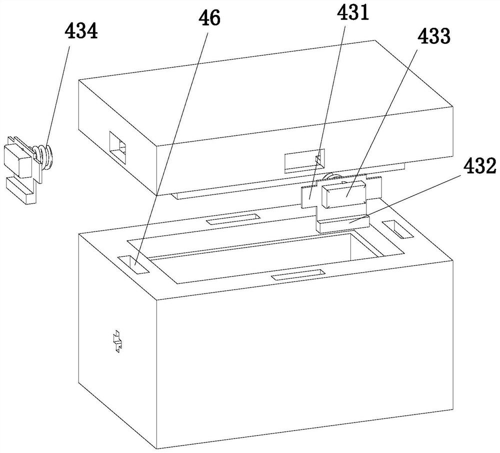
[0026] In this embodiment, if Figure 1 to Figure 7 As shown, a kind of auxiliary equipment for concrete product mold demoulding to ensure safe demoulding, including a workbench 1...


PUM


Abstract

The invention relates to the technical field of auxiliary equipment for mold demolding, and discloses auxiliary equipment for concrete product mold demolding and capable of guaranteeing safe demolding. The auxiliary equipment for concrete product mold demolding and capable of guaranteeing safe demolding comprises a workbench, an n-shaped frame, supporting legs, a storage assembly, a lifting assembly, a rotating assembly, a knocking assembly and a clamping assembly, wherein two supporting legs are arranged; the two supporting legs are installed at the bottom of the workbench in a spaced mode, the n-shaped frame is installed at the top of the workbench, the storage assembly is located between the n-shaped frame and the workbench, the lifting assembly is slidably arranged between the two supporting legs, and the top of the lifting assembly penetrates through the bottom of the workbench and is connected with the bottom of the storage assembly in an inserted mode; and the rotating assembly is installed on the side wall of the n-shaped frame. The auxiliary equipment for concrete product mold demolding and capable of guaranteeing safe demolding has the following advantages: through cooperation of the lifting assembly and the knocking assembly, the situation that a concrete product is prone to being damaged due to the fact that force cannot be guaranteed through manual collision is avoided, the labor intensity of workers is reduced, and the demolding efficiency is increased.

Description

technical field [0001] The present application relates to the technical field of mold demoulding auxiliary equipment, in particular to an auxiliary equipment for mold demoulding of concrete products that ensures safe demoulding. Background technique [0002] As the construction industry continues to evolve, so does the concrete industry. The quality control of ready-mixed concrete requires that the concrete be sampled during the production process for strength testing, and the concrete sampling test adopts a 150mm×150mm×150mm standard plastic test mold. After the concrete is formed, it is necessary to manually demould the specimen. After the mold is brushed with release agent, manual demoulding still has the problem of difficult demoulding. The current commonly used demoulding method is to turn the test piece 180° and then use a pressurized air pump to pump air into the reserved hole at the bottom of the test mold, and pressurize to extrude the test mold. This method parti...

Claims


Application Information

Patent Timeline
Patent Type & Authority Applications(China)
IPC IPC(8): B28B13/06
CPCB28B13/06B28B13/067
Inventor 刘晓彬叶蔚绿
Owner 深圳市汉工造技术有限公司
Learn More