An automatic water circulation system for a thermal power plant

A technology of water cycle and thermal power plant, applied in the field of water cycle, can solve the problems of cumbersome treatment methods and so on

Active Publication Date: 2022-06-21
华能伊敏煤电有限责任公司汇流河热电分公司 +1
View PDF6 Cites 0 Cited by
  • Summary
  • Abstract
  • Description
  • Claims
  • Application Information

AI Technical Summary

Problems solved by technology

However, the general treatment method of the above-mentioned thermal power plants is relatively cumbersome, and the circulating water with more impurities needs to be discharged first, and then re-flowed into the circulating water system, which delays the normal cooling work progress, and the existing technology has room for improvement

Method used


Image

  • An automatic water circulation system for a thermal power plant
  • An automatic water circulation system for a thermal power plant
  • An automatic water circulation system for a thermal power plant

Examples


Embodiment 1

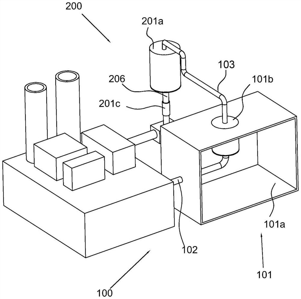
[0030] refer to Figure 1-5 , an automatic water circulation system for a thermal power plant, comprising, a circulation pipeline 100, including a distillation part 101, a water inlet pipe 102 directly connected to the distillation part 101, and a water outlet pipe 103 arranged at the other end of the distillation part 101, the water outlet pipe 103 and the water inlet pipe 102 There is a control valve on it; the condensation pipe 201b road 200 includes a condensation part 201 arranged at the end of the water outlet pipe 103 and a water circulation part arranged in the condensation part 201, and the other end of the water circulation part is provided with a water delivery part 202; and a cleaning assembly 400, The cleaning assembly 400 is connected to the water delivery unit 202 and the distillation unit 101 .

[0031] Specifically, the main structure of the present invention includes a circulation pipeline 100. In this embodiment, the circulation pipeline 100 includes a disti...

Embodiment 2

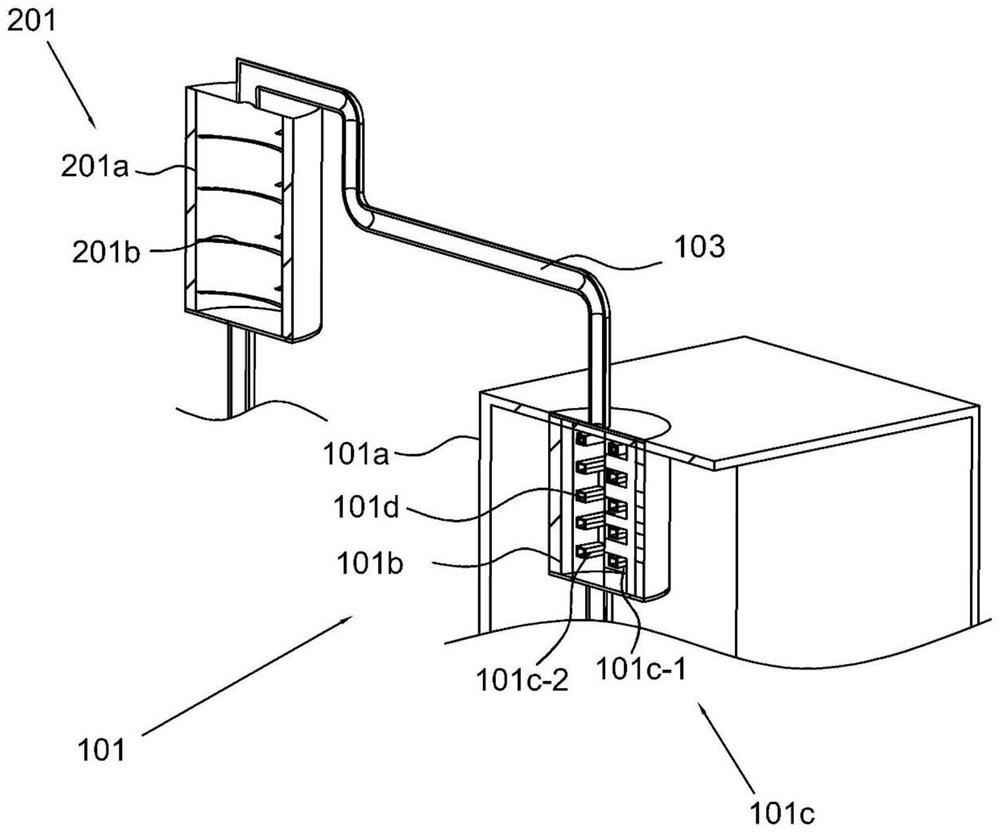
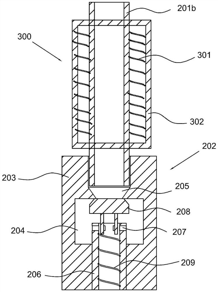
[0036] refer to Figure 1-5, this embodiment is different from the first embodiment in that the distillation part 101 includes a box body 101a, a distillation box arranged in the box body 101a and a heating element 101c arranged in the distillation box, and a heating tower 101b is arranged in the distillation box , the heating tower 101b is provided with a heating pipe 101d connected to the water inlet pipe 102, the heating pipe 101d is extended upward and is connected to the water outlet pipe 103, and the heating element 101c includes a heating hole 101c- 1. The heating wire 101c-2 arranged in the heating hole 101c-1 and the coating layer arranged outside the heating wire 101c-2, the coating layer is arranged in contact with the heating tube 101d, and the condensing element 201 includes a casing 101a provided The condensation chamber 201a at the upper position, the condensation pipe 201b spirally arranged in the condensation chamber 201a, and the outlet valve 201c arranged at...

Embodiment 3

[0045] refer to Figure 1-5 , this embodiment is different from the above embodiments in that the cleaning assembly 400 includes a water filter pipe 401 disposed at the end of the water pipe directly connected from the water delivery member 202, a filter screen 402 disposed in the water filter pipe 401, and a filter 402 that is rotatably connected to the The adsorption roller 403 at the rear end of the filter screen 402, wherein the adsorption roller 403 is provided with a clean water tank 404, and a switch plate 405 is rotatably connected to the notch of the clean water tank 404. The switch plate 405 is provided with a number of water filtering holes 405a. The inside of 405 is provided with a water filter bag 406, the water filter bag 406 is provided with volcanic stone debris, the upper end of the switch plate 405 is provided with a waste outlet 407, the water filter pipe 401 is rotatably connected with an opening plate 408, and the opening plate 408 and the water filter pipe...


PUM


Abstract

The invention discloses an automatic water circulation system of a thermal power plant, comprising: a circulation pipeline, including a distillation piece, a water inlet pipe directly connected to the distillation piece, and a water outlet pipe arranged at the other end of the distillation piece; the water outlet pipe and the water inlet pipe are provided with Control valve; condensing pipeline, including a condensing element arranged at the end of the water outlet pipe and a water circulation element arranged in the condensing element, the other end of the water circulation element is provided with a water delivery component; and a cleaning assembly, the cleaning assembly and the water delivery component Connected to the distillation unit.

Description

technical field [0001] The present invention relates to the technical field of water circulation, in particular to an automated water circulation system for thermal power plants. Background technique [0002] The circulating water system is an important cooling system to maintain the normal operation of the power plant, and the circulating water cooling system often uses a cooling tower to achieve the cooling operation of the circulating water. Evaporation) heat exchange effect, so as to achieve the purpose of removing waste heat. However, during the evaporation of circulating water, a large number of soluble ions dissolved in the water are precipitated and aggregated to produce scale, and the scale remains in the cooling tower for a long time, and will accumulate and adsorb on the surface of the heat exchanger, resulting in a decrease in the heat exchange efficiency of the cooling tower. , resulting in energy loss, reduced production capacity and increased equipment mainte...

Claims


Application Information

Patent Timeline
Patent Type & Authority Patents(China)
IPC IPC(8): C02F9/10F25D17/02C02F103/02
CPCC02F1/048C02F1/001F25D17/02C02F2103/023
Inventor 赵扬辛福利韩艳水孙昌海关鹏寇成宝裴立伟朱亚坤苗玉王正佳
Owner 华能伊敏煤电有限责任公司汇流河热电分公司
Why Eureka
Try Eureka