Method for selecting measuring head of three-coordinate measuring machine

A three-coordinate measuring machine and measuring head technology, which is applied to measuring devices, instruments, etc., can solve problems such as the failure of the measuring head to be used normally, shorten the service life of the measuring head, and the falling off of the force measuring module, so as to ensure effective acquisition and shorten the measurement time. time, avoiding the effect of measuring angles

Active Publication Date: 2021-08-03
CHENGDU AIRCRAFT INDUSTRY GROUP
View PDF15 Cites 2 Cited by
  • Summary
  • Abstract
  • Description
  • Claims
  • Application Information

AI Technical Summary

Problems solved by technology

If the selection of the probe is unreasonable, it will lead to unpredictable results such as the force measuring module falling off, the probe cannot be used normally to obtain effective signals, the measurement accuracy will be affected, and the service life of the probe will be shortened.

Method used


Image

  • Method for selecting measuring head of three-coordinate measuring machine
  • Method for selecting measuring head of three-coordinate measuring machine
  • Method for selecting measuring head of three-coordinate measuring machine

Examples


Embodiment 1

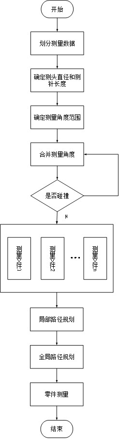
[0024] A method for CMM probe selection such as Figure 1-Figure 3 shown, including the following steps:

[0025] Step 1: Divide the measurement data: put the measurement data of the same feature of the part to be tested in the same data file;

[0026] Step 2: Determine the probe diameter and stylus length: In the data file, within the optional standard range of the CMM, determine the probe diameter and stylus length based on the principle of the length of the ball and rod;

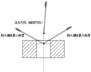
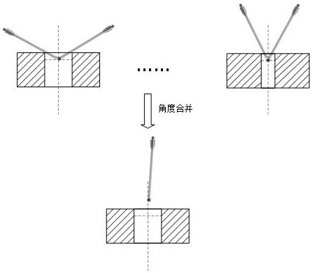
[0027] Step 3: Initially determine the measurement angle and combine the measurement angles: eg figure 2 As shown in , the touch direction of the probe is preliminarily determined by the direction of the measuring point, and the deflection angle range of the probe is preliminarily determined based on the principle of not touching the part to be tested; image 3 As shown, and then further based on the principle of non-collision parts and tooling, the initially determined deflection angle ranges of multi...

Embodiment 2

[0031] This embodiment is optimized on the basis of Embodiment 1. In the step 2, select the probe with the largest probe diameter to determine the diameter of the side probe, so as to improve the early triggering of the probe; select the longest probe to determine the diameter of the probe. length to increase the measurable characteristics of the stylus on the part being tested.

[0032] Further, the deflection angle of the probe is determined from the measurement angle determined in step 3, so as to ensure that the geometric features of the part to be measured are detected at the same probe angle. This embodiment overcomes unforeseen technical problems such as unreasonable selection of the measuring head, which will cause the force measuring module to fall off, the measuring head cannot be used normally to obtain effective signals, affect the measurement accuracy, and shorten the service life of the measuring head.

[0033] Other parts of this embodiment are the same as those...

Embodiment 3

[0035] A method for CMM probe selection such as figure 1 shown, including the following steps:

[0036] Step 1: Divide the measurement data: put the measurement data of the same feature of the part to be tested in the same data file;

[0037] Step 2: Determine the probe diameter and stylus length: In the data file, within the optional standard range of the CMM, determine the probe diameter and stylus length based on the principle of the length of the ball and rod;

[0038] Step 3: Initially determine the measurement angle and combine the measurement angles: eg figure 2 As shown in , the touch direction of the probe is preliminarily determined by the direction of the measuring point, and the deflection angle range of the probe is preliminarily determined based on the principle of not touching the part to be tested; image 3 As shown, and then further based on the principle of non-collision parts and tooling, the initially determined deflection angle ranges of multiple probes...


PUM


Abstract

The invention discloses a method for selecting a measuring head of a three-coordinate measuring machine. The method comprises the following steps of: sequentially dividing measurement data, determining the diameter of the measuring head and the length of a measuring needle, preliminarily determining a measurement angle, combining the measurement angles, extracting the same measurement point positions of the measuring head and placing the same measurement point positions in the same measurement file; in the measurement file, sequencing the measurement points according to the shortest path principle to complete local path planning; and connecting the head and tail measurement points in different measurement files in series according to the principle of shortest distance to complete sorting, so that the shortest walking path of the measurement head is ensured. According to the invention, reasonable selection of the diameter of the measuring head, the size of the measuring needle and the measuring angle can be realized, effective acquisition of measuring signals is ensured, planning of a measuring path is completed according to the characteristics of the measuring head, the precision and efficiency of part measurement are ensured, and the practicability is good.

Description

technical field [0001] The invention belongs to the technical field of three-coordinate measurement, and in particular relates to a method for selecting a measuring head of a three-coordinate measuring machine. Background technique [0002] Three-coordinate measuring machines are widely used in machinery manufacturing, aerospace and other fields due to their high precision, high efficiency, and many other features. They are the leading testing equipment for quality control in automated production. With the development of intelligent manufacturing, the processing efficiency of CNC machine tools is getting higher and higher, and more and more parts with complex shapes need to complete the inspection demonstration quickly and reliably. Therefore, higher speed and precision requirements are put forward for the three-coordinate measuring machine. How to ensure that the three-coordinate measuring machine can still achieve high-precision measurement at high speed is the primary pro...

Claims


Application Information

Patent Timeline
Patent Type & Authority Applications(China)
IPC IPC(8): G01B21/02G01B21/10G01B21/22
CPCG01B21/02G01B21/10G01B21/22
Inventor 武琼徐延豪马飞
Owner CHENGDU AIRCRAFT INDUSTRY GROUP
Why Eureka
Try Eureka