High-frequency broadband frequency hopping signal generation device and method based on photon technology

A broadband frequency hopping and signal generation technology, applied in the field of microwave photonic signal generation, can solve problems such as stability easily affected by the environment, poor tuning performance, performance deterioration, etc., to offset slight environmental interference, no transmission delay difference, low The effect of transmission loss

Active Publication Date: 2021-08-03
AIR FORCE UNIV PLA
View PDF7 Cites 6 Cited by
  • Summary
  • Abstract
  • Description
  • Claims
  • Application Information

AI Technical Summary

Problems solved by technology

[0004] However, the above schemes have certain limitations: Scheme (1) can only generate 2-order frequency hopping signals, and to generate multi-order frequency hopping signals, it is necessary to perform cascading / serial link structure, which leads to complex systems and performance degradation; scheme ( 2) The signal modulation rate, frequency hopping rate, and bandwidth of scheme (3) are limited by direct modulation lasers or tunable filters, and the stability is easily affected by the environment; in scheme (4), there are many devices that implement frequency-time mapping It has the disadvantages of large volume, poor tuning performance, and difficult operation.

Method used


Image

  • High-frequency broadband frequency hopping signal generation device and method based on photon technology
  • High-frequency broadband frequency hopping signal generation device and method based on photon technology
  • High-frequency broadband frequency hopping signal generation device and method based on photon technology

Examples


Embodiment Construction

[0027] The present invention will be further described below in conjunction with the accompanying drawings.

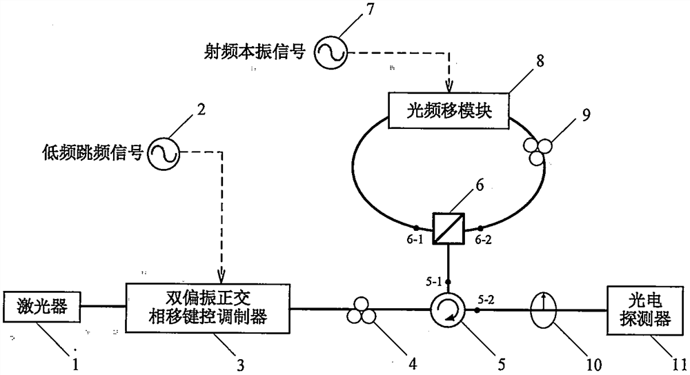
[0028] A device for generating high-frequency broadband frequency-hopping signals based on photonic technology, such as figure 1 As shown, it includes laser 1, low frequency frequency hopping signal 2, dual polarization quadrature phase shift keying modulator (DPQPSKM) 3, polarization controller A4, optical circulator 5, polarization beam splitter 6, radio frequency local oscillator signal 7, Optical frequency shift module 8, polarization controller B 9, analyzer 10, photodetector 11, 5-1 and 5-2 are respectively the first output end and second output end of optical circulator 5, 6-1 and 6-2 are the first output end and the second output end of the polarization beam splitter 6, respectively. The laser 1 is connected to the dual-polarization quadrature phase-shift keying modulator 3, and the optical carrier output by the laser 1 is modulated by the low-frequency freque...


PUM


Abstract

The invention provides a high-frequency broadband frequency hopping signal generation device based on a photon technology. The device comprises a laser, a low-frequency frequency hopping signal, a dual-polarization quadrature phase shift keying modulator DPQPSKM, a polarization controller, an optical circulator, a polarization beam splitter, a radio frequency local oscillator signal, an optical frequency shift module, an analyzer and a photoelectric detector. An optical modulator is used for carrying out electro-optical modulation on optical carriers and low-frequency frequency hopping signals output by a laser source to generate two paths of polarized orthogonal dual-wavelength optical signals, interference occurs after the two paths of polarized orthogonal dual-wavelength optical signals pass through a polarization controller, two paths of polarized orthogonal single-frequency optical signals are obtained, the two paths of polarized orthogonal single-frequency optical signals enter a Sagnac ring structure in the clockwise/anticlockwise transmission direction respectively, and single-frequency optical signal of the forward input optical frequency shift module is modulated to generate frequency shift; and the signals are polarized and combined by a polarization analyzer and then enter a detector for beat frequency, so that frequency multiplication and up-conversion operations on the low-frequency frequency hopping signals are realized. According to the invention, the working frequency band of the low-frequency frequency hopping signal is improved to a high-frequency domain by using an optical means, the working bandwidth is multiplied, the system control is flexible, and the tuning range is large.

Description

technical field [0001] The invention belongs to the technical field of microwave photon signal generation, and in particular relates to a photon technology-based high-frequency broadband frequency-hopping signal generation device and method thereof. Background technique [0002] Microwave frequency hopping signals are widely used in wireless communication, radar detection, electronic warfare and other fields. With the advancement of technology, the requirements for microwave frequency hopping signals in these application scenarios are increasingly expanding in the direction of high-frequency domain and large bandwidth. High-frequency broadband frequency-hopping signals can effectively increase communication transmission capacity, improve radar detection accuracy, improve anti-jamming capabilities and reduce the probability of being intercepted in electronic countermeasures. However, due to the existence of electronic bottlenecks, the frequency-hopping signal bandwidth (~100...

Claims


Application Information

Patent Timeline
Patent Type & Authority Applications(China)
IPC IPC(8): H04B10/50H04B1/7136
CPCH04B10/50H04B10/503H04B1/7136
Inventor 王国栋赵尚弘李轩朱子行蒋炜高从芮黄蓝锋李赫孟晴晴周逸潇
Owner AIR FORCE UNIV PLA
Why Eureka
Try Eureka