Disinfectant spraying device for ward in infectious disease department

A technology of spraying device and disinfectant, which is applied in the direction of spraying device and chemistry, can solve the problems of inability to fully disinfect, the space cannot be used for disinfection, and the inconvenience of observing the remaining amount of disinfectant, so as to reduce the occupied space, facilitate movement, Solve the effect of inconvenient observation

Active Publication Date: 2021-08-06
THE FIRST AFFILIATED HOSPITAL OF ZHENGZHOU UNIV
View PDF13 Cites 0 Cited by
  • Summary
  • Abstract
  • Description
  • Claims
  • Application Information

AI Technical Summary

Problems solved by technology

[0003] In view of the above situation, in order to overcome the defects of the prior art, the present invention provides a disinfectant spraying device for infectious disease wards, which effectively achieves the purpose of collecting the patient's mattress and solves the problem that the larger environment cannot be fully sterilized. It avoids the defect of disinfectant precipitation, adds the function of packing bedding, solves the problem that the small space cannot be disinfected, achieves the function of disinfecting the ground, and adds the function of changing the angle of the nozzle when spraying. It achieves the purpose of easy movement of the device, solves the problem of inconvenient observation of the remaining amount of disinfectant, and reduces the working pressure of medical staff

Method used


Image

  • Disinfectant spraying device for ward in infectious disease department
  • Disinfectant spraying device for ward in infectious disease department
  • Disinfectant spraying device for ward in infectious disease department

Examples


Embodiment 1

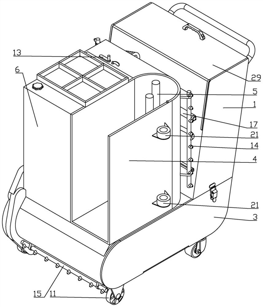
[0025] Embodiment one, by Figure 1-4Provided, the present invention includes a car body 1, in order to achieve the purpose of placing the patient's bedding, a placement groove 2 is provided in the car body 1, and the packed bedding can be put into the placement groove 2, in order to facilitate the removal of the bedding, The right side of the car body 1 is rotatably connected with a pick-and-place plate 3. In order to prevent the pick-and-place plate 3 from overturning automatically, the upper end of the pick-and-place plate 3 is provided with a tower buckle. A U-shaped groove 4 is fixedly connected, and a bed-rolling disc 5 is rotatably connected in the U-shaped groove 4. The upper end of the bed-rolling disc 5 is provided with two cylindrical rods. During use, the bedding is put into the U-shaped groove 4, and then Place one end of the bedding on the central position of the bedding disc 5, and the bedding is wound on the outside of the cylindrical rod by rotating the beddin...

Embodiment 2

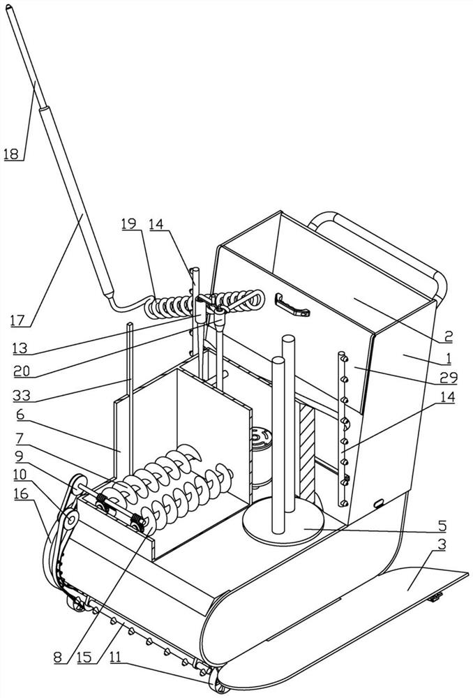
[0026] Embodiment two, on the basis of embodiment one, by image 3 and Figure 4 Given, in order to achieve the purpose of uniform spraying of disinfectant, the swing mechanism 12 includes an active clutch disc 34 slidingly connected with the first stirring rod 7, the active clutch disc 34 is set on the outside of the first stirring rod 7, and can be moved along the The first stirring rod 7 slides and rotates with the first stirring rod 7 at the same time. A U-shaped connecting rod 35 is set on the outside of the active clutch disc 34, and a reset extension spring 36 is fixedly connected to the rear end of the U-shaped connecting rod 35. The other end of the spring 36 is fixedly connected with the liquid storage tank 6, the lower end of the U-shaped connecting rod 35 is sleeved on the outside of the active clutch disc 34, and the front end of the U-shaped connecting rod 35 is rotationally connected with the liquid storage tank 6, and the active clutch disc 34 The front end of...

Embodiment 3

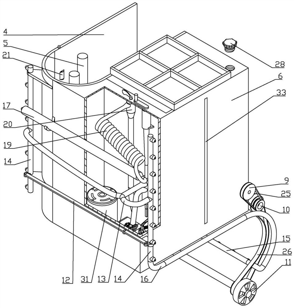
[0027] Embodiment three, on the basis of embodiment one, by Figure 4-7 and Figure 10 Given, in order to achieve the purpose of controlling spraying, the spraying mechanism 13 includes a sliding sleeve 43 fixedly connected with the vehicle body 1, the middle part of the sliding sleeve 43 is slidingly connected with a push link 44, and the push link 44 The upper end is rotatably connected with a rocker 45, and the rocker 45 is rotatably connected with the car body 1. When the rocker 45 rotates, the height of the rocker 45 will not change relative to the car body 1. A screw groove 46 is provided on the outer side of the lower end of the rocker 45. , the upper end of the push link 44 is provided with a bump corresponding to the position of the screw groove 46, the bump is placed in the screw groove 46 and can slide along the screw groove 46, the screw groove 46 is a two-section groove, the upper and lower sections and the middle All are provided with a smooth section, which eff...


PUM


Abstract

A disinfectant spraying device for a ward in the infectious disease department effectively solves the problems that an existing device cannot collect bedding of a patient and disinfection is incomplete in a relatively large environment; the disinfectant spraying device comprises a vehicle body; a containing groove is formed in the vehicle body; a U-shaped groove is formed in the upper end of the vehicle body; a bedding rolling disc is arranged in the U-shaped groove; a liquid storage box is arranged on the left side of the U-shaped groove; a first stirring rod is arranged in the liquid storage box; a swing mechanism is arranged at the rear end of the liquid storage box; a spraying mechanism is arranged above the swing mechanism; longitudinal spraying pipes are arranged on the left side and the right side of the vehicle body respectively; the first stirring rod and the swing mechanism are matched with each other to form a limiting structure of each longitudinal spraying pipe; and a transverse spraying pipe is arranged at the rear end of the vehicle body. The disinfectant spraying device in the invention is novel in structure and smart in conception; by means of the design, the defect that disinfectant precipitates is effectively overcome; the bedding packaging function is added; the problem that sterilization cannot be conducted in a narrow space is solved; the ground sterilization function is achieved; and the function that the angle of a spray head can be changed during spraying is newly added.

Description

technical field [0001] The invention belongs to the technical field of medical disinfection devices, and in particular relates to a disinfectant spraying device for infectious disease wards. Background technique [0002] The Department of Infectious Diseases mainly treats infectious diseases. Among infectious diseases, viral hepatitis, AIDS, and tuberculosis are the most common. Of course, it also includes other infectious diseases, such as chickenpox measles, malaria parasite infection, fungal infection, influenza virus infection, bird flu virus infection, hand, foot and mouth disease and other infectious diseases, so the infectious disease ward needs to be disinfected frequently, and The bedding after use by patients also needs to be treated separately. Disinfectant solution is usually made of disinfectant effervescent tablets or high-concentration disinfectant solution diluted with water in a certain ratio to form a suitable concentration disinfectant solution, which is u...

Claims


Application Information

Patent Timeline
Patent Type & Authority Applications(China)
IPC IPC(8): A61L2/18B05B15/25B05B15/00
CPCA61L2/18B05B15/25B05B15/00Y02A50/30
Inventor 王秀静张雪雪王晓娟毛静潘舒婷
Owner THE FIRST AFFILIATED HOSPITAL OF ZHENGZHOU UNIV
Why Eureka
Try Eureka