Surface anti-hardness machining system for core rod machining

A processing system and mandrel technology, which is applied in the surface anti-hard machining system and the field of mandrel surface treatment, can solve the problem of reducing processing production efficiency, manual adjustment of lateral dimensions and horizontal alignment, and affecting mandrel anti-hard machining work Efficiency and other issues, to achieve the effect of stable and efficient anti-hard treatment, avoid spraying liquid leakage, convenient and efficient detection

Pending Publication Date: 2021-08-06
天津滨海龙泰科技发展有限公司
View PDF0 Cites 0 Cited by
  • Summary
  • Abstract
  • Description
  • Claims
  • Application Information

AI Technical Summary

Problems solved by technology

[0003] The spraying treatment is mainly to form a coating film on the surface of the mandrel through the migration of the positive and negative electrodes of the electrification to realize the hard-resistant processing technology. The existing spraying equipment is relatively traditional, and the shunt effect is poor; the uneven spraying on the surface of the mandrel is the influence The main technical problem of resistance to hard machining, and the mandrel transfer structure is only a single carriage, and the lateral dimension and horizontal alignment need to be manually adjusted.
[0004] The large error and time-consuming operation greatly affect the work efficiency of the mandrel surface against hard machining, especially the processing requirements of mandrels of various specifications cannot be met; in addition, spraying processing fluid will be generated after the mandrel surface is sprayed. , usually all need to be recycled. The recycling in the prior art is relatively simple, usually a simple recovery tank or a recovery bucket, which is inefficient and prone to leakage, which reduces the processing and production efficiency and if the recovered liquid cannot be handled well, it will be harmful to the Production poses safety hazards and is not environmentally friendly

Method used


Image

  • Surface anti-hardness machining system for core rod machining
  • Surface anti-hardness machining system for core rod machining
  • Surface anti-hardness machining system for core rod machining

Examples


Embodiment Construction

[0028] The present invention will be further described in detail below in conjunction with the accompanying drawings and through specific embodiments. The following embodiments are only descriptive, not restrictive, and cannot limit the protection scope of the present invention.

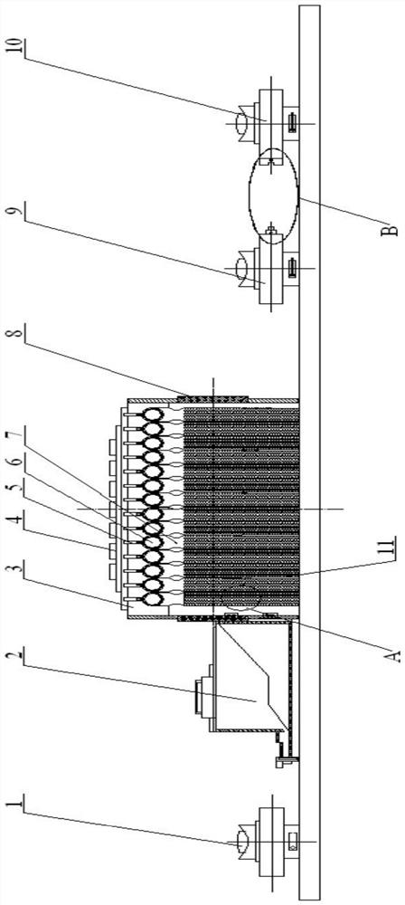
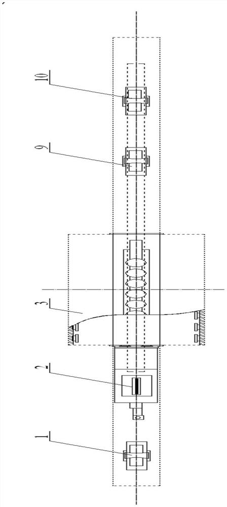
[0029] A surface resistant hard machining system for mandrel machining such as figure 1 , figure 2 As shown, it includes a transmission unit, a spraying unit 4 and a liquid recovery unit 2, the transmission unit and the spraying unit are arranged on the bottom plate, the liquid recovery unit is arranged at the mandrel outlet end of the spraying unit, and the transmission unit It includes a mobile conveying group and a fixed trailer 1. The conveying group is arranged on the slide rail of the mandrel inlet side bottom plate of the spraying unit, and the fixed trailer is arranged on the bottom plate of the mandrel outlet end of the spraying unit.

[0030] Described mobile transmission group comprises ...


PUM


Abstract

The invention relates to a surface anti-hard machining system for core rod machining. The surface anti-hard machining system comprises a conveying unit, a spraying unit and a liquid recovery unit, the conveying unit and the spraying unit are arranged on a bottom plate, the liquid recovery unit is arranged at the core rod outlet end of the spraying unit, the conveying unit comprises a movable conveying group and a fixed trailer, the conveying group is arranged on a sliding rail of a bottom plate on the side of the core rod inlet end of the spraying unit, and the fixed trailer is arranged on a bottom plate at the core rod outlet end of the spraying unit. The surface anti-hard machining system is scientific and reasonable in design, the conveying unit, the spraying unit and the liquid recovery unit are effectively integrated, and a lattice structure is innovated and improved, so that the problems of conveying, spraying and treatment liquid recovery in core rod spraying are effectively solved, the core rod surface anti-hard machining process efficiency can be effectively improved, and the system is further suitable for popularization and application in spraying of other long-axis workpieces.

Description

technical field [0001] The invention belongs to the field of mandrel processing, and relates to a mandrel surface treatment technology, in particular to a surface anti-hard processing system for mandrel processing. Background technique [0002] The mandrel is a long-axis workpiece, which is a deformation tool in the production of seamless steel pipes. It has a long length and is a workpiece used under extremely harsh conditions of high temperature and high pressure, so it requires high processing technology. In order to improve the wear resistance and pressure resistance of the mandrel during use, it is necessary to carry out anti-hard processing on the surface of the mandrel. It does not deform or fall off under the action of the mandrel. It is usually necessary to spray the surface of the mandrel to meet the higher technical parameter requirements. [0003] The spraying treatment is mainly to form a coating film on the surface of the mandrel through the migration of the p...

Claims


Application Information

Patent Timeline
Patent Type & Authority Applications(China)
IPC IPC(8): B05B5/08B05B5/16B05B14/00
CPCB05B5/084B05B5/16B05B14/00Y02P70/10
Inventor 黄平王梅王文起
Owner 天津滨海龙泰科技发展有限公司
Why Eureka
Try Eureka