Negative pressure type microorganism grouting device

A microbial and negative pressure technology, applied in the field of negative pressure microbial grouting device, can solve problems such as dependence, and achieve the effect of reducing production cost and improving work efficiency

Pending Publication Date: 2022-01-07
HUNAN INSTITUTE OF ENGINEERING
View PDF0 Cites 0 Cited by
  • Summary
  • Abstract
  • Description
  • Claims
  • Application Information

AI Technical Summary

Problems solved by technology

At present, there are few grouting methods for experiments in the laboratory, and most of them rely on peristaltic pumps and other grouting equipment. There is still a lot of room for improvement.

Method used


Image

  • Negative pressure type microorganism grouting device
  • Negative pressure type microorganism grouting device
  • Negative pressure type microorganism grouting device

Examples


Embodiment 1

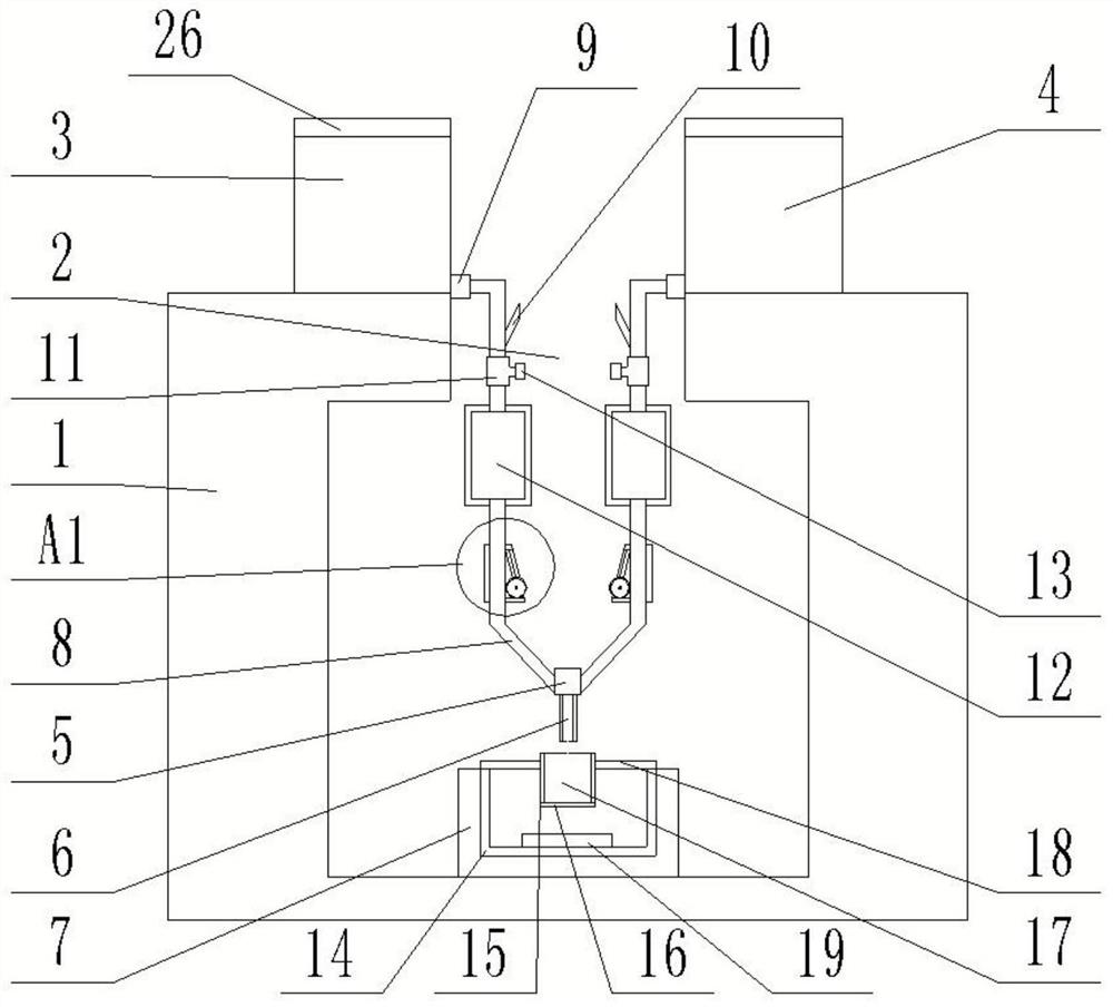
[0023] refer to Figure 1-2 , the present invention provides a negative pressure microbial grouting device, which is characterized in that it includes: a test case 1, a communication hole 2 is provided on the top surface of the test case 1, and a nutrient solution cylinder 3 and a mixed liquid cylinder are provided on the top surface of the test case 1 4. The nutrient solution cylinder 3 and the mixing liquid cylinder 4 are arranged symmetrically with respect to the communication hole 2. The outer walls of the bottom of the nutrient solution cylinder 3 and the mixing liquid cylinder 4 are connected with a drip irrigation mechanism. Connected with a conduit 6, the bottom surface of the inner cavity of the test shell 1 is provided with a constant temperature box 7, and a sample is arranged in the constant temperature box 7, and the conduit 6 corresponds to the position of the sample;

[0024] The drip irrigation mechanism includes a hose 8, the tops of the two hoses 8 communicat...

Embodiment 2

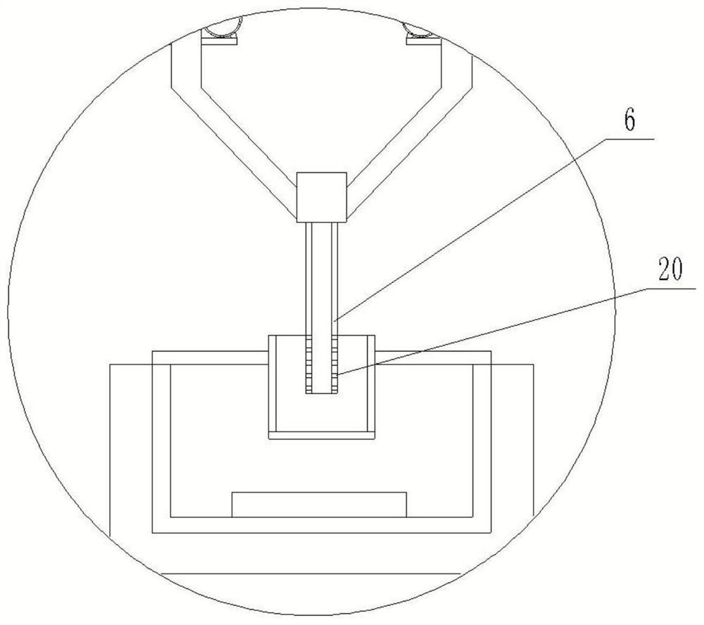
[0039] refer to image 3 , to further optimize the scheme, the bottom of the outer wall of the conduit 6 is provided with a number of penetration holes 20, the top of the conduit 6 communicates with the bottom of the stopcock 5, the bottom end of the conduit 6 is set inside the sample body 17, and several penetration holes 20 are located in the sample body Within 17.

[0040] The arrangement of the permeable holes 20 can realize grouting inside the sample body 17 and improve the grouting efficiency.

Embodiment 3

[0042] refer to Figure 4 , the support seat 18 includes a support ring 27, the support ring 27 is sleeved outside the sample cylinder 15, a number of clamping mechanisms are arranged at equal intervals on the inner wall of the support ring 27, and a number of observation mechanisms are arranged at equal intervals on the top surface of the support ring 27 in the circumferential direction. The hole 28, the top surface of the support ring 27 abuts against the top surface of the connecting cylinder 14; the clamping mechanism and the observation hole 28 are arranged at intervals;

[0043] The clamping mechanism includes a clamping rod 29, one end of the clamping rod 29 is fixedly connected with a rubber pad 30, the inner wall of the support ring 27 is provided with a clamping groove 31, and the other end of the clamping rod 29 is located in the clamping groove 31, and the clamping groove 31 both sides are provided with reset groove 32, and snap-in rod 29 both sides are affixed wit...


PUM


Abstract

The invention discloses a negative pressure type microorganism grouting device which is characterized by comprising a test shell, a communication hole is formed in the top surface of the test shell, a nutrient solution barrel and a mixed solution barrel are arranged on the top surface of the test shell and are symmetrically arranged about the communication hole, and the outer walls of the bottoms of the nutrient solution barrel and the mixed solution barrel are each communicated with a drip irrigation mechanism; the bottoms of the two drip irrigation mechanisms are communicated through a plug valve, the bottom surface of the plug valve is communicated with a guide pipe, the bottom surface of an inner cavity of the test shell is provided with a constant-temperature box, and a sample is arranged in the constant-temperature box;the drip irrigation mechanisms comprises hoses, and the top ends of the two hoses are communicated with the bottoms of the mixed solution barrel and the nutrient solution barrel respectively; the hoses are communicated with shut-off valves at the communicated parts of the bottoms of the mixed solution barrel and the nutrient solution barrel; the hoses are sequentially communicated with breather pipes, dosing three-way joints, drip chambers and flow regulators from top to bottom; the air inlet ends of the breather pipes are communicated with the outer walls of the hoses and the outside air, and the dosing three-way joints are communicated with the dosing droppers.

Description

technical field [0001] The invention relates to the technical field of civil engineering foundation treatment and reinforcement, in particular to a negative pressure microbial grouting device. Background technique [0002] In the field of civil engineering foundation treatment and reinforcement, grouting technology based on cement, lime or chemical slurry is a very common method of foundation reinforcement. Microbial grouting is a new type of green reinforcement technology. Compared with traditional cementitious materials, it has the advantages of low viscosity, good fluidity, strong permeability, adjustable reaction rate and bonding strength, and less environmental pollution. It belongs to low energy consumption and low emission materials. At present, there are few grouting methods for experiments in the laboratory, and most of them rely on grouting equipment such as peristaltic pumps. There is still a lot of room for improvement. Based on this understanding, the inventor...

Claims


Application Information

Patent Timeline
Patent Type & Authority Applications(China)
IPC IPC(8): G01N1/28E02D3/12
CPCG01N1/28E02D3/12
Inventor 梁桥伍硕果李小华曾宪桃严名佳
Owner HUNAN INSTITUTE OF ENGINEERING
Why Eureka
Try Eureka