A waste treatment device for shearing and punching machines used in furniture production
A waste material treatment and punching machine technology, which is applied in the direction of presses, manufacturing tools, etc., can solve the problems of inability to ensure the closing effect of rectangular holes, inability to share the power of shearing and punching machines, and high energy consumption in production, so as to avoid poor sealing effect and ensure The effect of repeating normal use and reducing production energy consumption
- Summary
- Abstract
- Description
- Claims
- Application Information
AI Technical Summary
Problems solved by technology
Method used
Image
Examples
Embodiment 1
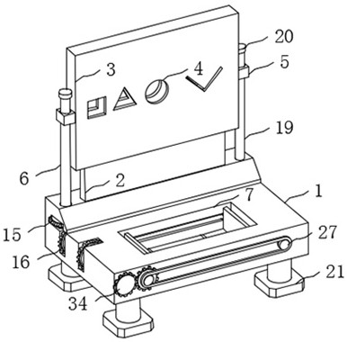
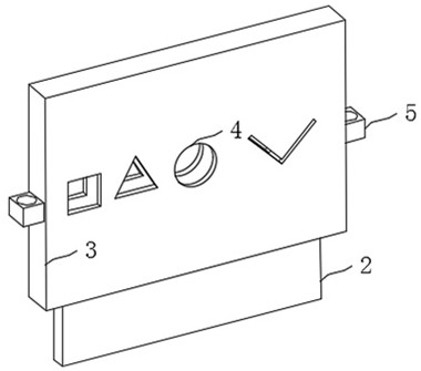
[0035] refer to Figure 1-2 , a kind of scrap processing device for shearing and punching machines used in furniture production, comprising a cutting knife 2 fixedly installed on a mounting base 1, a cutting die 3 is installed on the mounting base 1, and a cutting die 3 matched with the cutting die 3 is provided on the cutting die 3. The cavity, the front and rear side walls of the cutting mold 3 are provided with a plurality of placement holes 4 of different shapes, and each placement hole 4 communicates with the cutting cavity. When cutting the plate, it is placed in the cutting mold 3 The corresponding shape of the back is placed in the hole 4, and it is completely passed through the cutting mold 3, and then the cutting mold 3 is moved down, and the cutting effect of the cutting knife 2 can be used to complete the cutting of the plate.
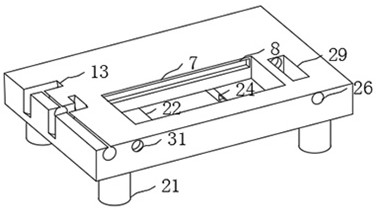
[0036] The mounting seat 1 is provided with a lifting mechanism matched with the cutting die 3 , and the lifting mechanism is composed of ...
Embodiment 2
[0051] refer to Figure 9 The difference between the second embodiment and the first embodiment is that the adjustment mechanism is composed of a pull block, a magnetic plate and a magnetic block, the pull block is fixedly installed on the lower end of the baffle plate 23, and the magnetic plate is fixedly installed on the front side wall of the baffle plate 23, The magnetic block is fixedly installed on the front end side wall of the discharge groove 22, and the magnetic block corresponds to the position of the magnetic plate. They are all inclined to the direction of the treatment tank 7. For the specific inclination method, refer to Figure 9 .
[0052] The advantage of Embodiment 2 over Embodiment 1 is that the components used in the adjustment mechanism are relatively simple, which can effectively reduce the production cost of the device. At the same time, the switch of the discharge tank 22 can be manually selected according to the stock of leftover materials in the tre...
PUM
 Abstract
Description
Claims
Application Information
 - R&D
- Intellectual Property
- Life Sciences
- Materials
- Tech Scout
- Unparalleled Data Quality
- Higher Quality Content
- 60% Fewer Hallucinations
Browse by: Latest US Patents, China's latest patents, Technical Efficacy Thesaurus, Application Domain, Technology Topic, Popular Technical Reports.
© 2025 PatSnap. All rights reserved.Legal|Privacy policy|Modern Slavery Act Transparency Statement|Sitemap|About US| Contact US: help@patsnap.com


