A hydraulic pressure booster

A hydraulic and pressurized plate technology, applied in forging/pressing/hammering machinery, forging press driving device, forging/pressing/hammer device, etc., can solve problems such as low working speed, reduced life span, and large structure, and achieve Improve production efficiency, increase forming force, and reduce cost

Active Publication Date: 2022-08-02
HENAN UNIV OF SCI & TECH
View PDF6 Cites 0 Cited by
  • Summary
  • Abstract
  • Description
  • Claims
  • Application Information

AI Technical Summary

Problems solved by technology

Generally, a large hydraulic press is used to solve the problem, but the large hydraulic press has a huge structure, high price, complex hydraulic system, and low working speed, which greatly increases the production cost.
[0003] Using a hydraulic press with a conventional pressurization mechanism will greatly increase the height of the hydraulic cylinder, which is useless for a hydraulic press with a large stroke; and a hydraulic press with a pressurization mechanism will reduce its life and the probability of leakage due to the high pressure on the control pipeline

Method used


Image

  • A hydraulic pressure booster

Examples


Embodiment 1

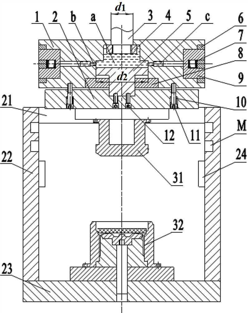
[0028] The specific structure of one of the embodiments of the present invention will be described in detail below in conjunction with the accompanying drawings: figure 1 As shown, a hydraulic pressurizing mechanism, the pressurizing mechanism includes a constraining frame and a pressurizing mechanism, the constraining frame includes a horizontal plate 21, a vertical plate 22 and a bottom plate 23 that are integrally connected, and the vertical plate 22 is provided with pin holes M and fixedly connected with a stopper 24;

[0029] In this embodiment, the booster mechanism is composed of a booster plate 1 with a combined hydraulic chamber a and a lateral locking mechanism for locking the position of the booster plate 1 . From top to bottom in the vertical direction, there are a small-diameter pressure chamber and a large-diameter pressurization chamber in order. Passing through the pressurizing plate 1 and having a protruding end for connecting with the movable beam of the pre...


PUM


Abstract

A hydraulic pressurizing mechanism, the pressurizing mechanism comprises a pressurizing plate and a lateral locking mechanism for locking the position of the pressurizing plate, the pressurizing plate has a combined hydraulic chamber, and the combined hydraulic chamber is in the combined hydraulic chamber From top to bottom in the vertical direction, there are a small-diameter pressure chamber and a large-diameter pressurization chamber in sequence. and has a protruding end, the protruding end is used for connecting with the movable beam of the press; the pressurizing chamber is slidably fitted with a pressurizing piston, and the lower end of the pressurizing piston passes through the pressurizing plate and is connected to the pressing piece. In this scheme, without changing the overall structure of the press, the pressurizing mechanism can be directly matched to the press, which can amplify the pressure of the equipment and greatly increase the forming force. Large metal parts are formed on smaller hydraulic presses.

Description

technical field [0001] The invention relates to the technical field of hydraulic forming equipment, in particular to a hydraulic pressurizing mechanism. Background technique [0002] At present, when the hydraulic press is used for the precision forming of large metal parts such as extrusion, precision forging and liquid die forging, a large forming force is often required to meet the requirements of material deformation; Modulo space requirements. In this regard, large-scale hydraulic presses are generally used to solve the problem, and large-scale hydraulic presses have large structures, high prices, complex hydraulic systems, and low working speeds, thus greatly increasing production costs. [0003] The use of a hydraulic press with a conventional booster mechanism will greatly increase the height of the hydraulic cylinder, which is powerless for a hydraulic press with a large stroke; and a hydraulic press with a booster mechanism controls the high pressure of the pipeli...

Claims


Application Information

Patent Timeline
Patent Type & Authority Patents(China)
IPC IPC(8): B21J9/12B21J13/02B21J13/00
CPCB21J9/12B21J13/02B21J13/00
Inventor 杨茜杨永顺虞跨海
Owner HENAN UNIV OF SCI & TECH
Why Eureka
Try Eureka