Mechanical arm cutting guide rail for manufacturing industrial automatic control device
A technology of an automatic control device and a robotic arm, applied in the field of industrial manufacturing, can solve the problems of equipment being easily damaged and stuck, inconvenient for special-shaped shapes, and difficult to clean, and achieves the effects of improving quality, reducing damage, and facilitating centralized processing.
- Summary
- Abstract
- Description
- Claims
- Application Information
AI Technical Summary
Problems solved by technology
Method used
Image
Examples
Embodiment 1
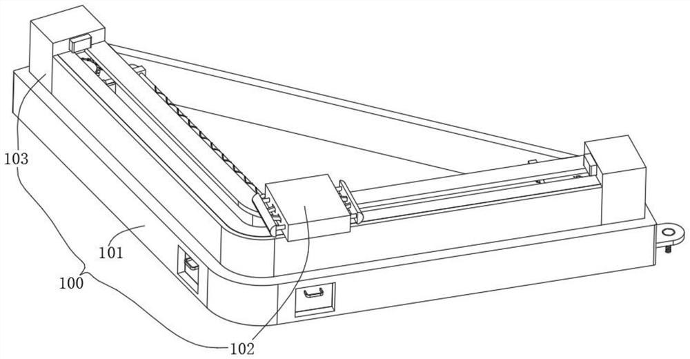
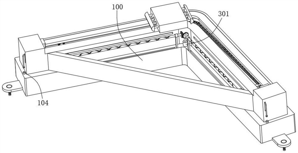
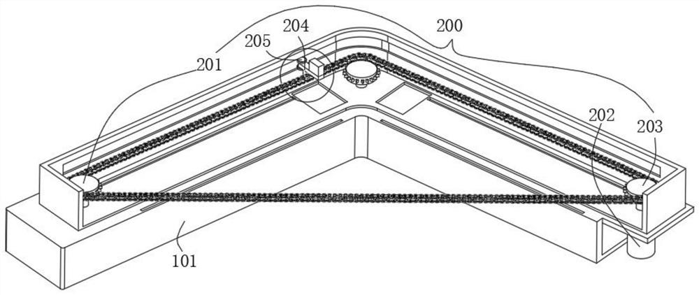
[0050] Combine figure 1 , 2 3 and 4, the industrial automatic control device provided by the present invention is manufactured by a robotic arm cutting guide, including a rail body 100, a transmission mechanism 200, a cleaning mechanism 300, a buffer mechanism 400, and a brake mechanism 500, and the rail body 100 comprises a housing. 101. The base 102 provided on the housing 101 is opened on the housing 101 and the emergency button 104 provided on both sides on the housing 101, the housing 101 is a V-shaped shape, and the transmission mechanism 200 includes rotatable. The driven sprocket 201 mounted in the middle and one side of the housing 101, the first motor 202 is fixed to the housing 101, and the active sprocket 203 is fixed to the first motor 202 output, the drive is connected to the driven chain. The chain on the wheel 201 and the active sprocket 203 and the transmission bracket 204 fixed to the chain, the tip of the transmission frame 204 extends over the housing 101 and i...
Embodiment 2
[0054] Combine Figure 5 , 6 As shown in the case, in the first embodiment, the cleaning mechanism 300 includes a second motor 301 fixed to the housing 101, and is fixed to the first cone 302 of the second motor 301 output, which rotatably mounted to the shell. The reciprocating wire rod 303 on both sides of the body 101 is fixed to the second cone 304 that engages the transmission of the first cone 302 end portion and the first tapered gear 302, which is suitable for the relative to the retro bar 303, rotatable mounting The shaft on the connecting block 306 is sleeved on the cleaning roller 308 and the first gear 309 and the first gear 309 fixed to the housing 101 and the first gear 309, and one end of the rotating shaft extends through the slide. Inside the casing 101, the bottom of the connecting block 306 is fixed, and one end of the slider is slidably coupled to the casing 101 by the slide. The staff first moves the transmission bracket 204 to the middle of the housing 101, an...
Embodiment 3
[0058] Combine figure 1 and 8 As shown in the above embodiment, the buffer mechanism 400 includes a support rod secured to the base 102, a sliding block 402, which is suitable for sliding on both sides of the support rod, is disposed in the inner side wall of the base 102 and the sliding block 402. A spring 403 is hinged on the connecting strip on both sides of the sliding block 402 and the anti-collision block 401 of the hinged connection strip end, and when the device is abnormal, the movement of the base 102 cannot be controlled, the base 102 moves to both sides, when the base When 102 is hit, the anti-collision block 401 pushes the sliding block 402 by a connecting strip such that the two sliding blocks 402 move toward both sides, the sliding block 402 is extruded, and the first spring 403 absorbs the force generated by the impact. Then, it is possible to make a buffer, reduce the impact on the robotic arm on the base 102 to generate damage, which is advantageous to improve th...
PUM
 Abstract
Description
Claims
Application Information
 - R&D Engineer
- R&D Manager
- IP Professional
- Industry Leading Data Capabilities
- Powerful AI technology
- Patent DNA Extraction
Browse by: Latest US Patents, China's latest patents, Technical Efficacy Thesaurus, Application Domain, Technology Topic, Popular Technical Reports.
© 2024 PatSnap. All rights reserved.Legal|Privacy policy|Modern Slavery Act Transparency Statement|Sitemap|About US| Contact US: help@patsnap.com


