
Machine tool chip rolling device for machining

A machining and chip rolling technology, applied in metal processing equipment, metal processing mechanical parts, manufacturing tools, etc., can solve problems such as waste of resources, reduce costs, increase storage space, and ensure waste of resources.

Inactive Publication Date: 2021-08-06
JIANGSU SECURITY TECH CARRER ACADEMY
View PDF0 Cites 1 Cited by
  • Summary
  • Abstract
  • Description
  • Claims
  • Application Information

AI Technical Summary

Problems solved by technology

[0005] The purpose of the present invention is to solve the following shortcomings in the prior art. Coolant is often used during machining, and at this time, there will often be residual coolant on the iron chips transported by the chip rolling machine, which will cause unnecessary damage in the long run. The waste of resources, in the traditional chip rolling machine only transports and collects the chips generated on the machine tool, and there is no other auxiliary equipment to collect and reuse the liquid remaining on the chips, and proposes a machine tool for mechanical processing Chip rolling device

Method used


Image

  • Machine tool chip rolling device for machining
  • Machine tool chip rolling device for machining
  • Machine tool chip rolling device for machining

Examples


Embodiment Construction

[0029] Next, the technical solutions in the embodiments of the present invention will be apparent from the embodiment of the present invention, and it is clearly described, and it is understood that the described embodiments are merely embodiments of the present invention, not all of the embodiments.

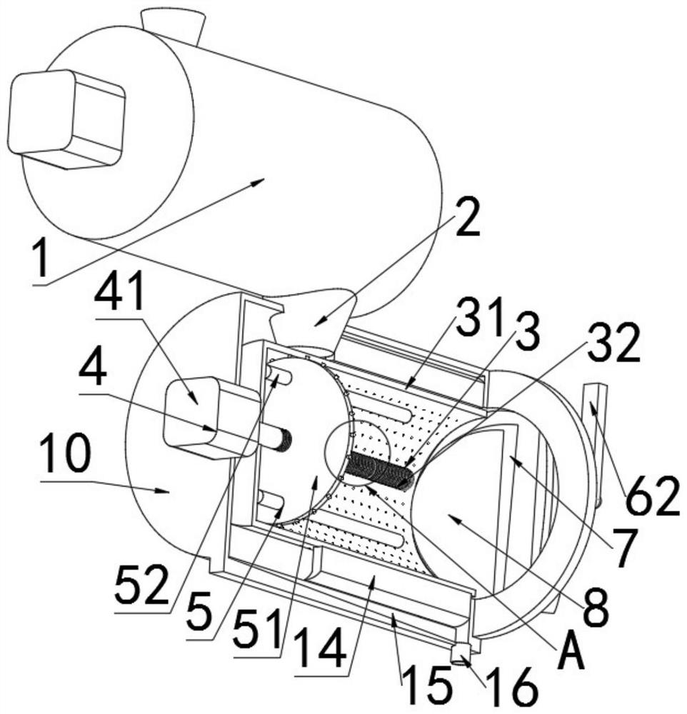
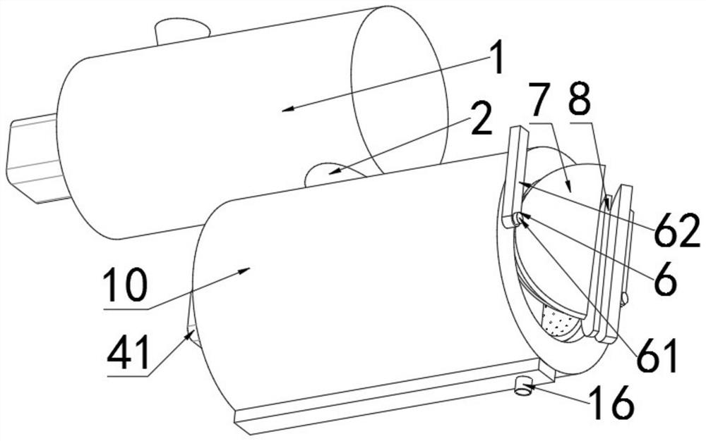
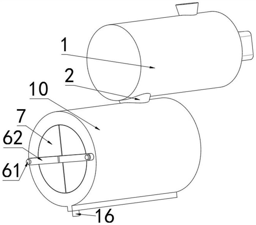
[0030] Refer Figure 1-5 , A machine tool for machining, including;

[0031] Vechnoid assembly 1, a crimping assembly 1 for transporting winding of seggers such as chipped parts produced on machine tools, and the disoelectric assembly 1 is mainly a crimping machine whose type includes a blade type, chain plate type, magnetic type As well as the spiral crimping machine, mainly used to transport the crumbs produced on the machine, and the working principle is the prior art, and will not be described later;

[0032] The cylindrical body 10 is opened in the cylinder 10, and the cylindrical 10 is used to collect and secondary processing, and the crimping assembly 1 is opened by the crimpi...


PUM


Abstract

The invention discloses a machine tool chip rolling device for machining. The machine tool chip rolling device comprises a chip rolling assembly and a barrel body, wherein the chip rolling assembly is used for transporting and rolling chip wires and the like generated by machining parts on a machine tool; a first cavity is formed in the barrel body; and the barrel body is used for collecting and secondarily machining the chip wires transported by the chip rolling assembly and is connected with the chip rolling assembly through a discharge port formed in the chip rolling assembly. According to the machine tool chip rolling device, through cooperative work of a rotary barrel, a driving component and a plurality of through holes formed in the rotary barrel, when the chip wires reach the interior of the rotary barrel from the chip rolling assembly, the rotary barrel rotating at a high speed drives the chip wires to rotate, residual cooling liquid on the chip wires falls onto the inner side wall of the barrel body through the through holes under the action of centrifugal force, is collected on a water tank under the action of a scraper and then flows out through a water outlet, so that the residual cooling liquid on the chip wires is collected and reused, unnecessary resource waste is guaranteed, and the cost is reduced.

Description

Technical field [0001] The present invention relates to the field of machining equipment, and more particularly to a machine tool for machining. Background technique [0002] Metal processed debris, generally in the process of performing metal equipment, often causes different sizes of debris, and if it is not collected, it will affect the service life of the processing equipment and affect the quality of product processing. [0003] The crimp machine is mainly used to transport the metal generated by machining and metal scraps, common blade, chain plate type, magnetic and spiral crimping machine. [0004] When machining, the coolant is often used, and the iron filings transported by the consisted chips will often remain residual, and there will be unnecessary resources for waste, only on the traditional crimping machine. The resulting debris is transported, and there is no other auxiliary device to collect reuse of the residual liquid on debris. Inventive content [0005] It is...

Claims


Application Information

Patent Timeline
Patent Type & Authority Applications(China)
IPC IPC(8): B23Q11/00
CPCB23Q11/0042
Inventor 李丽红张发海
Owner JIANGSU SECURITY TECH CARRER ACADEMY
Learn More