Cutting tooth assembly with wear sensing device, roller and coal mining machine
A sensing device and pick technology, which is applied in the field of pick components, drums and shearers, can solve the problem of late intervention time, and achieve the effect of improving operation safety and reducing costs
- Summary
- Abstract
- Description
- Claims
- Application Information
AI Technical Summary
Problems solved by technology
Method used
Image

Examples
Embodiment 1
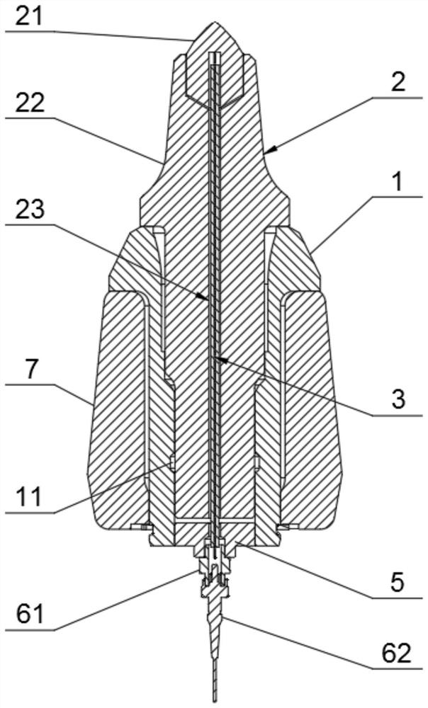
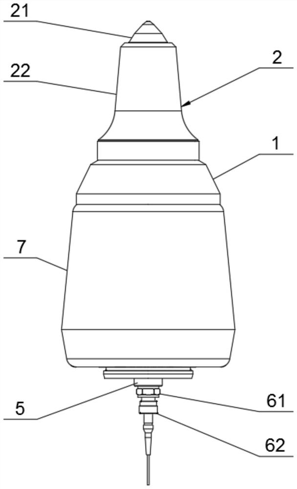
[0047] Such as Figure 1 to Figure 3 As shown, a pick assembly with a wear sensing device includes a pick collar 1 , a pick 2 , an optical fiber sensor 3 and a data acquisition device 4 .
[0048]The pick 2 and the pick collar 1 are fixedly connected by a snap ring 11, and the snap ring 11 fixes the pick 2 and the pick collar 1 on the tooth holder 7 together. Wherein, the pick 2 and the pick collar 1 pass through the first snap ring groove at the tail of the pick base 22 and the second snap ring groove that matches the inner hole of the pick collar 1 at the corresponding position, and the first snap ring groove located in the first snap ring groove. It is fixedly connected with the snap ring 11 in the second snap ring groove, and the snap ring 11 is a piston type snap ring;
[0049] A shaft snap ring is arranged outside the root of the pick collar 1, and the shaft snap ring connects the pick collar 1 and the tooth seat 7 as a whole by cooperating with the end of the pick coll...
Embodiment 2
[0054] On the basis of Embodiment 1, this embodiment may also include the following:
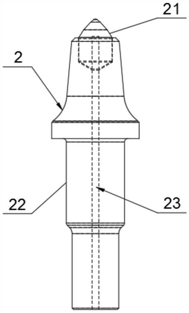
[0055] see Figure 4 As shown, the optical fiber sensor 3 of the present embodiment may include an optical fiber 31 and a sheath 32, and the optical fiber sensor 3 is provided with sensing units in different distances in stages as the measuring point 33, and the sheath 32 is coated with the optical fiber 31 through a microhole fixed-point glue injection process. The synthetic optical fiber sensor 3 can ensure that the measuring points 33 do not affect each other during the wear process. Further, the diameter of the optical fiber 31 is 0.25-0.5 mm, and the outer diameter of the sheath 32 is 2-3 mm. The size of the sheath 32 is mainly to consider that the diameter of the mounting hole 23 of the pick 2 should not be greater than 5 mm, and to ensure that the sheath 32 is in contact with the There is a certain gap between the optical fibers 31, thereby ensuring that the rotation process of the p...
Embodiment 3
[0060] On the basis of the foregoing embodiments, this embodiment may also include the following:
[0061] Such as Figure 5-8 As shown, the optical fiber sensor 3 is communicatively connected with the data acquisition device 4 through the quick connector 62, the data acquisition device 4 transmits an optical signal to the optical fiber sensor 3, and each measuring point 33 of the optical fiber 31 will reflect the optical signal, and the data acquisition device 4 receives The light signals reflected by each measuring point 33 are sent to the monitoring terminal 8 to display the wear state of the pick 2 in real time. Wherein, what is transmitted in the optical fiber sensor 3 is an optical signal, and the transmission is stable and reliable, which can effectively make the pick 2 adapt to the harsh working environment underground. In particular, stable testing can be guaranteed in a water environment; it is not interfered by electromagnetic signals generated during the operation...
PUM
 Abstract
Description
Claims
Application Information
 - Generate Ideas
- Intellectual Property
- Life Sciences
- Materials
- Tech Scout
- Unparalleled Data Quality
- Higher Quality Content
- 60% Fewer Hallucinations
Browse by: Latest US Patents, China's latest patents, Technical Efficacy Thesaurus, Application Domain, Technology Topic, Popular Technical Reports.
© 2025 PatSnap. All rights reserved.Legal|Privacy policy|Modern Slavery Act Transparency Statement|Sitemap|About US| Contact US: help@patsnap.com