Device and method for stripping communication optical cable

A communication optical cable and optical cable technology, which is applied in the field of optical cable equipment, can solve the problems of easily damaged optical fibers, and achieve the effects of protecting optical fibers, reducing contact, cutting or pinch loss

Pending Publication Date: 2021-08-06
HOHAI UNIV
View PDF1 Cites 2 Cited by
  • Summary
  • Abstract
  • Description
  • Claims
  • Application Information

AI Technical Summary

Problems solved by technology

[0004] The purpose of the present invention is to provide a device and method for stripping communication optical cables, so as to overcome the technical problem in the prior art that the optical fibers are easily damaged when the optical fiber surface jacket is stripped

Method used


Image

  • Device and method for stripping communication optical cable
  • Device and method for stripping communication optical cable
  • Device and method for stripping communication optical cable

Examples


Embodiment Construction

[0034] The following will clearly and completely describe the technical solutions in the embodiments of the present invention with reference to the accompanying drawings in the embodiments of the present invention. Obviously, the described embodiments are only some, not all, embodiments of the present invention. Based on the embodiments of the present invention, all other embodiments obtained by persons of ordinary skill in the art without creative efforts fall within the protection scope of the present invention.

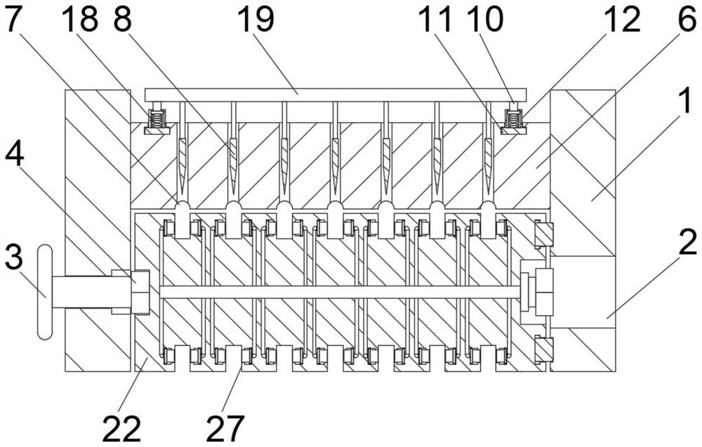
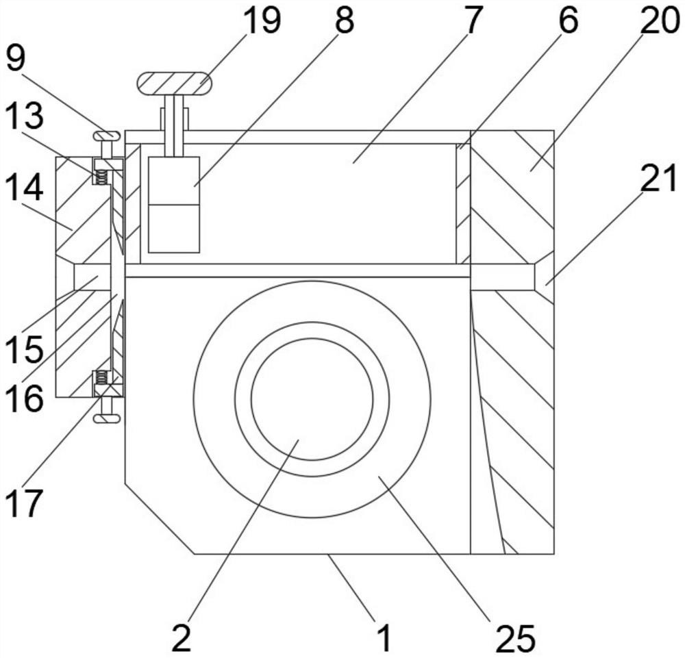
[0035] Such as Figure 8A device for unpacking a communication optical cable described in this embodiment includes a cover body 1, the cover body is in a U-shaped structure as a whole, and includes a connecting plate, and a side plate is provided at both ends of the connecting plate, which are respectively side plate one and Side plate 2, the shape of the two side plates is the same, a chamfer is formed between the front end surface and the bottom surface of the si...


PUM


Abstract

The invention discloses a device and method for stripping a communication optical cable. The front end face of a cover body is provided with a transverse cutting assembly, the rear end face of the cover body is connected with a side supporting seat, and the side supporting seat is provided with a plurality of observation holes at intervals; the part, close to the bottom, in the cover body is provided with a rotating assembly, and the outer surface of the rotating assembly is uniformly provided with a plurality of cable grooves; an optical cable needing to be peeled extends into the cable groove through the positioning hole and extends out of the device through the observation hole. A vertical cutting assembly is fixedly connected to the portion, above the rotating assembly, of the cover body, and a vertical cutter is connected to the vertical cutting assembly in a sliding mode. According to the invention, after the skin of the optical fiber is stripped, a worker pulls the optical cable towards one side of the positioning seat, so that each stripped skin can be taken down from the rotating frame, a bare fiber protection sleeve is embedded into the bottom side of each cable groove, and each bare fiber protection sleeve can be embedded into the surface of each optical fiber by rotating a hand wheel; therefore, the device can not only open and pull the optical cable, but also protect the optical fiber, and is convenient to use.

Description

technical field [0001] The invention relates to the technical field of optical cable equipment, in particular to a device and method for stripping a communication optical cable. Background technique [0002] When the optical cable enters the optical distribution equipment, the outer sheath of the optical cable must be stripped, the optical fiber is exposed, and a soft sleeve is used for protection. [0003] The structure of the conventional communication optical cable stripping tool, such as the application number 201721472594.1, and the invention name is the structure shown in the multi-functional leather cable optical cable stripping pliers. When in use, it needs to be twisted back and forth on the surface of the optical cable to facilitate the clamping of the optical cable jacket and being removed. Stripping, during which the pinch off part of the tool is likely to cause irreversible damage to the fiber itself. Contents of the invention [0004] The purpose of the pres...

Claims


Application Information

Patent Timeline
Patent Type & Authority Applications(China)
IPC IPC(8): G02B6/44G02B6/245
CPCG02B6/245G02B6/566
Inventor 李嘉颖朱嘉骏张泽宇史方磊
Owner HOHAI UNIV
Why Eureka
Try Eureka