Supercharge Your Innovation With Domain-Expert AI Agents!

SBG semiconductor laser device using electrode to realize sampling

A laser and semiconductor technology, applied in the field of optoelectronics, can solve the problems of increasing manufacturing cost, increasing sampling pattern lithography process, complex processing, etc., to achieve the effect of reducing complexity and manufacturing cost, improving threshold performance and quantum conversion efficiency

Pending Publication Date: 2021-08-06
CHANGZHOU INST OF TECH
View PDF7 Cites 0 Cited by
  • Summary
  • Abstract
  • Description
  • Claims
  • Application Information

AI Technical Summary

Problems solved by technology

Compared with the manufacture of uniform gratings, the manufacturing of sampling gratings, on the one hand, increases the lithography process of sampling patterns, which makes the processing more complicated and increases the manufacturing cost; on the other hand, the manufacturing of sampling gratings essentially removes part of the seed grating periodically (Uniform grating) process, so the sampling grating refractive index modulation intensity is smaller than that of the seed grating, so the SBG semiconductor laser frequency-selective grating (usually one of the sample grating ± 1-level sub-grating) has a feedback effect on the lasing wavelength ratio The seed raster is weaker
This results in a higher threshold and lower quantum conversion efficiency in actual SBG semiconductor lasers compared with uniform grating semiconductor lasers

Method used


Image

  • SBG semiconductor laser device using electrode to realize sampling
  • SBG semiconductor laser device using electrode to realize sampling
  • SBG semiconductor laser device using electrode to realize sampling

Examples


Embodiment 1

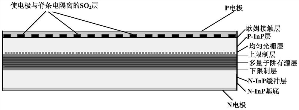
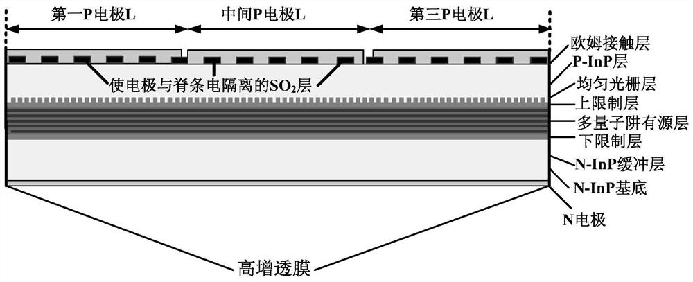
[0022] The present embodiment provides a kind of SBG semiconductor laser device that realizes sampling with three electrodes, as figure 2 As shown, the grating along the laser cavity is a uniform grating, which has three electrically isolated electrodes, and the center of the sampling pattern formed by the middle electrode and the conductive area between the ridges can be a uniform sampling pattern with or without equivalent phase shift. Both ends of the laser are coated with high anti-reflection coating.

[0023] The implementation principle of the fine adjustment of the lasing wavelength of the SBG semiconductor laser device in this embodiment is as follows:

[0024] we take figure 2 As an example to illustrate, for the sake of simplicity, let the lengths of the electrodes at both ends and the middle electrode be L R = L, L P =L, then when the electrodes at both ends of the laser are injected with the same current density and the middle electrode is injected with differ...

Embodiment 2

[0028] The present embodiment provides a kind of SBG semiconductor laser device that realizes sampling with two electrodes, as image 3 As shown, the grating along the laser cavity is a uniform grating, which has two electrically isolated electrodes, and the two ends of the laser are coated with high reflection film and high anti-reflection film respectively.

[0029] The implementation principle of the fine adjustment of the lasing wavelength of the SBG semiconductor laser device in this embodiment is as follows:

[0030] we take figure 2 As an example to explain, for the sake of simplicity, the lengths of the end electrodes coated with high anti-reflection coating and high reflection coating are respectively L P =L, then when the two electrodes of the laser are injected with different current densities, the effective refractive index n of the laser cavity under the two electrodes of the laser R and n P will be different, and also in the lasing channel will obtain a dis...


PUM


Abstract

The invention discloses an SBG semiconductor laser device using an electrode to realize sampling. A seed grating of the SBG semiconductor laser device is a common uniform grating, and a conductive region above an electrode and a ridge strip is designed into a sampling pattern shape, so that the feedback effect of a grating structure on light is the same as that of a sampling grating. According to the SBG semiconductor laser device, a sampling structure does not need to be introduced into the uniform grating, and the same feedback effect of the sampling grating on light and the selection effect on lasing wavelength can be realized.

Description

technical field [0001] The invention relates to the field of optoelectronic technology, and relates to optical fiber communication, photon integration, photoelectric sensing and other photoelectric information processing. The present invention is a method for making a uniform grating semiconductor laser device into a sampling grating (Sampling Bragg Grating, SBG) semiconductor laser device by using electrodes in the shape of a sampling pattern. Background technique [0002] In order to ensure the single-mode yield of the laser, in a distributed feedback (DFB) semiconductor laser, it is usually necessary to introduce a real phase shift into its frequency-selected uniform grating, and to manufacture this uniform grating with a real phase shift requires Electron beam exposure technology and equipment with processing precision of at least 0.1 micron level. However, if the sampling grating technology is used, the control of the sampling period of several microns to tens of micro...

Claims


Application Information

Patent Timeline
IPC IPC(8): H01S5/042H01S5/22
CPCH01S5/04256H01S5/2218
Inventor 周亚亭赵勤贤刘雨
Owner CHANGZHOU INST OF TECH
Features
  • R&D
  • Intellectual Property
  • Life Sciences
  • Materials
  • Tech Scout
  • Unparalleled Data Quality
  • Higher Quality Content
  • 60% Fewer Hallucinations
Learn More