
A uqpsk signal demodulation device

A signal demodulation and signal technology, applied in the direction of phase modulation carrier system, etc., can solve the problem that the ideal sampling and timing synchronization of the I-channel baseband signal and the Q-channel baseband signal cannot be satisfied at the same time, and the UQPSK signal reception and demodulation cannot be truly realized. Equipment reliability and stability, etc., to improve equipment stability and applicability, meet rapid development and upgrades, and improve implementation efficiency.

Active Publication Date: 2022-03-01
NO 54 INST OF CHINA ELECTRONICS SCI & TECH GRP
View PDF7 Cites 0 Cited by
  • Summary
  • Abstract
  • Description
  • Claims
  • Application Information

AI Technical Summary

Problems solved by technology

[0003] At present, although the demodulator using the variable sampling clock as a technical means can realize the carrier synchronization of the UQPSK signal in principle, but because its internal variable sampling clock can only support the control of a set of control quantities, it cannot simultaneously satisfy the I channel The ideal sampling and timing synchronization of the baseband signal and the Q baseband signal, so it is impossible to truly realize the reception and demodulation of the UQPSK signal
In addition, although the all-digital demodulator with intermediate frequency sampling and digital resampling as technical means can realize carrier synchronization of UQPSK signals and independent timing synchronization of I / Q two-way baseband signals in principle, it is necessary to design multiple sets of digital demodulators. Resampling the signal processing flow leads to high implementation complexity, a large amount of debugging, and a large increase in the required hardware logic resources, which affects the reliability and stability of the device

Method used


Image

  • A uqpsk signal demodulation device
  • A uqpsk signal demodulation device
  • A uqpsk signal demodulation device

Examples


Embodiment Construction

[0022] The present invention will be further described in detail below in conjunction with the accompanying drawings and specific embodiments.

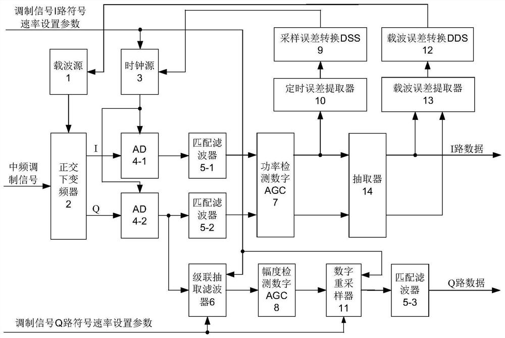
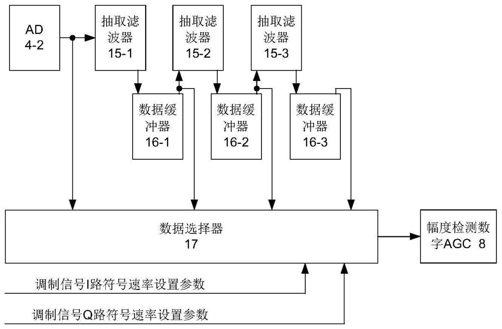
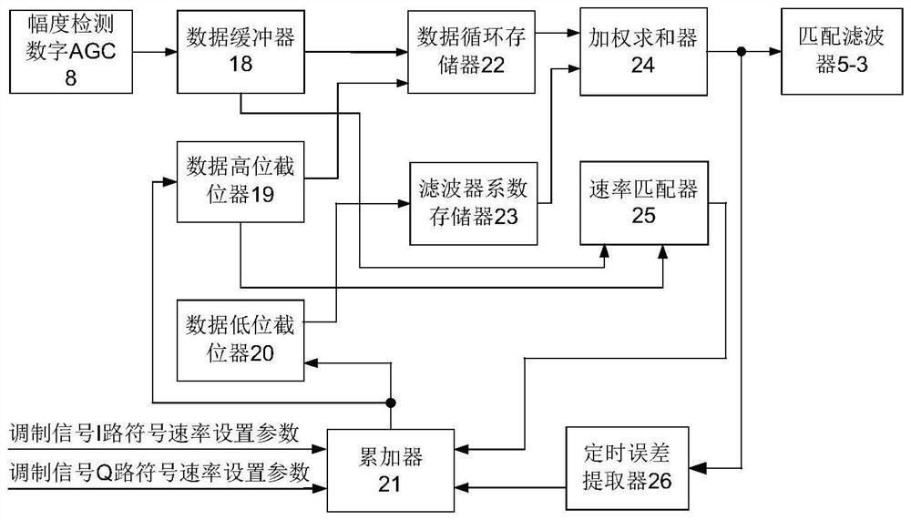
[0023] refer to figure 1 , a high symbol rate UQPSK signal demodulation device, which includes a carrier source 1, a quadrature down converter 2, a clock source 3, AD4-1 and AD4-2, a matched filter 5-1, and a matched filter 5-2 And matched filter 5-3, cascaded decimation filter 6, power detection digital AGC7, amplitude detection digital AGC8, sampling error conversion DDS9, timing error extractor 10, digital resampler 11, carrier error conversion DDS12, carrier error extraction device 13 and extractor 14. The quadrature down-converter 2 performs analog quadrature down-conversion on the input UQPSK modulation signal to generate I / Q two-way analog baseband signals, and the I / Q two-way analog baseband signals are respectively sampled by AD4-1 and AD4-2, Converted to I / Q two-way digital baseband signals, among which the Q-way digital b...


PUM


Abstract

The invention discloses a high symbol rate UQPSK signal demodulation device, which belongs to the technical field of communication and data transmission. The device consists of carrier source, quadrature down converter, clock source, AD converter, matched filter, cascaded decimation filter, power detection digital AGC, amplitude detection digital AGC, sampling error conversion DDS, timing error extractor, digital It consists of resampler, carrier error conversion DDS, carrier error extractor and decimator. The present invention aims at the application scenario where the I sub-band signal and the Q sub-band signal in the UQPSK signal are not generated from the same source, the symbol rate of the I / Q two-way signal is completely out of proportion, and the power of the I / Q two-way signal is completely out of proportion. Power detection is used respectively. Digital AGC and amplitude detection digital AGC, and integrated the signal processing flow of analog variable sampling clock, digital resampling and analog variable carrier, realized the automatic locking of high symbol rate baseband signal and low symbol rate baseband signal to I channel and Q channel respectively function of the road.

Description

technical field [0001] The invention relates to the technical field of communication and data transmission, in particular to a high symbol rate UQPSK signal demodulation device, which can be used for receiving and demodulating high symbol rate UQPSK signals in satellite communication and data receiving sub-systems of data ground receiving stations. Background technique [0002] The application conditions of the traditional UQPSK signal demodulation device require that the I sub-band signal and the Q sub-band signal are generated from the same source, and the symbol rate of the I sub-band signal is proportional to the symbol rate of the Q sub-band signal. The power of the Q-band signal is proportional to an integer. When the conditions cannot be fully satisfied, it will lead to unstable demodulation function or performance degradation. This requirement reduces the stability and applicability of the UQPSK signal demodulation device. [0003] At present, although the demodula...

Claims


Application Information

Patent Timeline
Patent Type & Authority Patents(China)
IPC IPC(8): H04L27/22
CPCH04L27/22
Inventor 李超贾耀红任立清李春祎
Owner NO 54 INST OF CHINA ELECTRONICS SCI & TECH GRP
Learn More