Pneumatic tire manufacturing method

A technology of pneumatic tires and manufacturing methods, which is applied in the field of manufacturing pneumatic tires and manufacturing pneumatic tires, can solve problems such as the difficulty of removing filmy burrs, and achieve the effect of reducing air resistance

Active Publication Date: 2021-08-06
THE YOKOHAMA RUBBER CO LTD
View PDF9 Cites 0 Cited by
  • Summary
  • Abstract
  • Description
  • Claims
  • Application Information

AI Technical Summary

Problems solved by technology

In addition, it is extremely difficult to remove protruding membranous flash from the tire surface

Method used


Image

  • Pneumatic tire manufacturing method
  • Pneumatic tire manufacturing method
  • Pneumatic tire manufacturing method

Examples


Embodiment

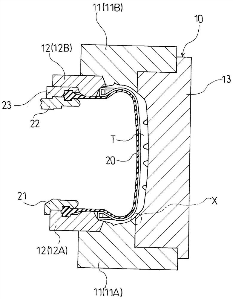
[0046] When a pneumatic tire having a tire size of 225 / 55R17 was vulcanized using a mold having a side plate for molding the side wall portion and a sector portion for molding the tread portion, the molds described above used various structures (conventional examples, Comparative Example 1 and Examples 1 to 4).

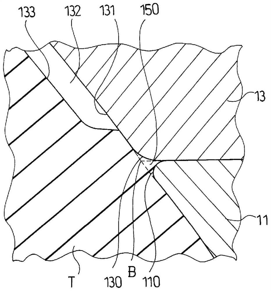
[0047] In the conventional example, in the edge portion where the side plate abuts the sector portion, the chamfered portion is formed only in the edge portion of the side plate. In Comparative Example 1, the chamfered portion was not formed in the edge portion where the side plate abutted against the fan-shaped portion. In Examples 1 to 4, a chamfered portion was formed in each of the edge portions where the side plate and the fan-shaped portion abutted.

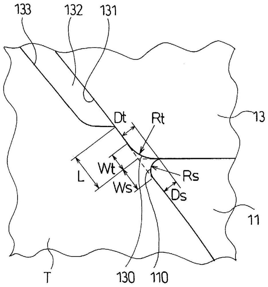
[0048] In the conventional example, Comparative Example 1, and Examples 1 to 4, as shown in Table 1, the shortest distance L from the virtual vertex of the edge portion of the sector to the groove-forming skeleton...


PUM

PropertyMeasurementUnit
widthaaaaaaaaaa
depthaaaaaaaaaa

Abstract

Provided is a pneumatic tire manufacturing method with which it is possible to efficiently eliminate an unnecessary projection formed on a tire surface at a dividing position between a side plate and a sector and thereby obtain a pneumatic tire in which air resistance is reduced. The manufacturing method comprises performing vulcanization by using a mold 10 that has a side plate 11 for molding a side wall part of a pneumatic tire T and a sector 13 for molding a tread part of the pneumatic tire T and forms chamfered parts 110 and 130 at an edge part at which the side plate 11 and the sector 13 are abutted on each other; forming a ridge 150 that extends in a tire circumferential direction along the chamfered parts 110 and 130 at the dividing position between the side plate 11 and the sector 13 in the pneumatic tire T vulcanized inside the mold 10; and cutting the ridge 150 with a cutter 170 along the tire circumferential direction.

Description

technical field [0001] The present invention relates to a method of manufacturing a pneumatic tire, and more particularly, to a method of manufacturing a pneumatic tire capable of effectively eliminating unnecessary protrusions formed on the tire surface at the divided positions between the side panels and the sector portions. so that a pneumatic tire with reduced air resistance can be obtained. Background technique [0002] When vulcanizing a pneumatic tire, a lower side plate and an upper side plate for forming a sidewall portion, a lower side bead ring and an upper side bead ring for forming a bead portion, and a tread portion forming A segmented mold with a plurality of fan-shaped portions (for example, refer to Patent Documents 1 to 3). [0003] When vulcanization is performed using the mold as described above, due to the structure of the vulcanizer, a height difference is formed at the dividing position between the side plate and the sector. In this case, in the obta...

Claims


Application Information

Patent Timeline
Patent Type & Authority Applications(China)
IPC IPC(8): B29D30/06B29C33/02B29C35/02B29L30/00
CPCB29D30/0629B29D2030/0607B29D30/0606B29D2030/0612
Inventor 渡边大辅
Owner THE YOKOHAMA RUBBER CO LTD
Why Eureka
Try Eureka