A medical hand-held portable sharps box
A portable, sharps box technology, applied in the field of medical devices, can solve the problems of high risk of being stabbed and infected, easy needle puncture for medical staff, low processing efficiency, etc., so as to enhance occupational safety and reduce occupational exposure. Opportunity, the effect of avoiding secondary damage
- Summary
- Abstract
- Description
- Claims
- Application Information
AI Technical Summary
Problems solved by technology
Method used
Image
Examples
Embodiment 1
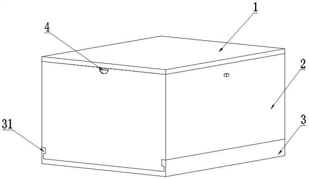
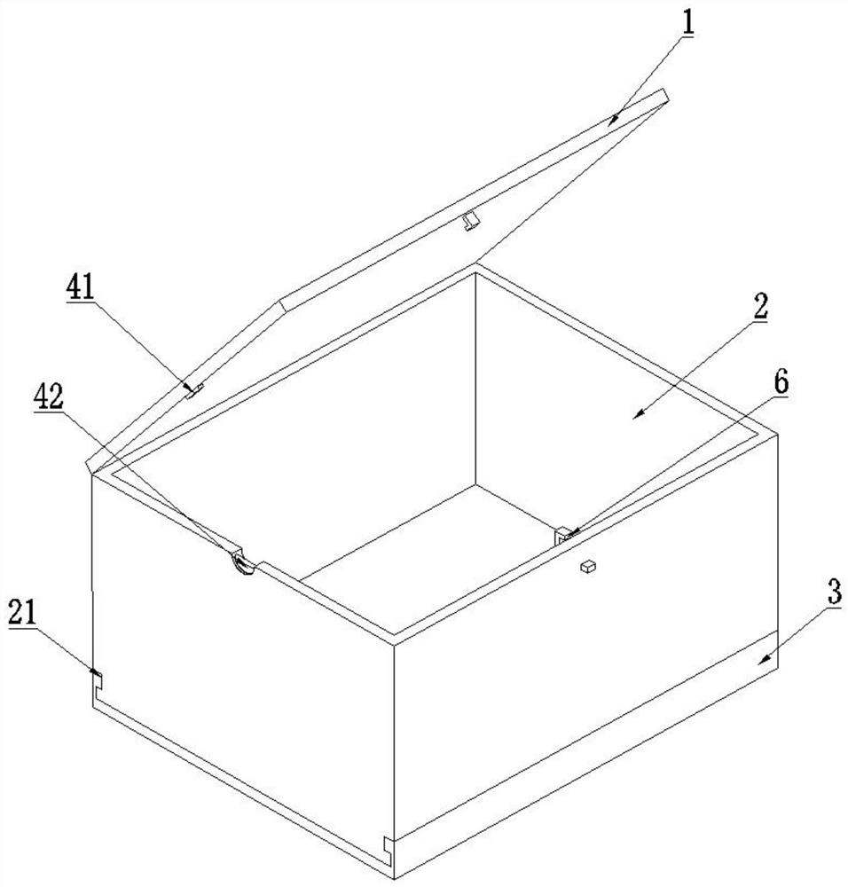
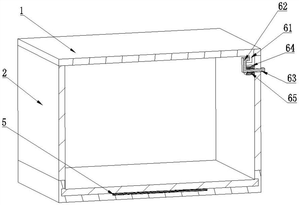
[0026] like Figure 1 to 3 As shown, a medical hand holds a portable sharpener box, including a cartridge 1, a casing 2, a cassette bottom 3, a cutting device 4, and an adsorption device 5, and the cartridge 1 is hinged, and the other The side is detachably connected to the casing 2 through the connecting device 6, the cutting device 4 is disposed at the abutment between the cartridge cover 1 and the casing 2, the cutting device 4 includes a support pad block 41 and a cutting mechanism. 42. The support space 41 is disposed on the lid 1 or the casing 2, the cutting mechanism 42 is mounted on the casing 2 or cartridge 1 corresponding to the support pad 41, the support pad block 41 Contact with the cutting mechanism 42, the cassette bottom 3 is disposed at the bottom end of the casing 2 and is detachably connected to the casing 2, the adsorption device 5 being mounted on the bottom 3 of the box.
[0027] Based on the above technical solution, a slot 21 is provided on the bottom side w...
Embodiment 2
[0034] Unlike the embodiment, if Figure 4 and Figure 5As shown, based on the above technical solution, the cutting mechanism 42 includes a storage blade 421, a drive shaft 422, a first cone gear 423, a second bevel gear 424, and a driven shaft 425, and the storage blade 421 is mounted in a box. In the groove of the inner side wall of the cover 1, the active shaft 422 is disposed on the cartridge cover 1, the first tapered gear 423 and one end of the active shaft 422, the second cone gear 424 and the first cone gear 423. Meshing, the driven shaft 425 is fixed to the second cone gear 424, and the other end is fixed to the storage blade 421, the support pad 41 being fixed to the casing 2. When the storage blade 421 in the cutting mechanism 42 and the casing 1 is formed, when the cartridge 1 is rotated, the lid 1 is rotated by the active shaft 422, the first cone gear 423, the second cone gear 424 And the drive shaft 425 is rotated by the rotating blade 421, and the rotating blade 421...
Embodiment 3
[0036] Unlike the embodiment, if Image 6 and Figure 7 As shown, based on the above technical scheme, the cutting mechanism 42 includes a rotating blade 426 and a driving motor 427, the rotating blade 426 mounted in an opening opened on the side wall of the casing 2, the drive motor 427 by transmission. The mechanism 428 drives the rotary blade 426 to rotate, the support pad 41 fixedly disposed on the inner side of the cartridge 1. The transmission mechanism employs a cone gear drive mechanism or a belt drive mechanism. By providing the rotating blade 426, a simpler and fast separation can be achieved between the hose and the sharpener; more preferably, in the position of the lid 1 support the pad 41, the same rotating blade 426 and the drive motor on the casing 2 427, the two rotating blade 426 rotate simultaneously and the direction of rotation is opposite, and the cropping effect of the hose and the sharpener is better.
PUM
 Abstract
Description
Claims
Application Information
 - R&D
- Intellectual Property
- Life Sciences
- Materials
- Tech Scout
- Unparalleled Data Quality
- Higher Quality Content
- 60% Fewer Hallucinations
Browse by: Latest US Patents, China's latest patents, Technical Efficacy Thesaurus, Application Domain, Technology Topic, Popular Technical Reports.
© 2025 PatSnap. All rights reserved.Legal|Privacy policy|Modern Slavery Act Transparency Statement|Sitemap|About US| Contact US: help@patsnap.com


