
Self-insulation composite wall body structure, installation mode, performance testing method and application of self-insulation composite wall body structure

A composite wall and installation technology, applied in the testing of machine/structural components, vibration testing, testing of mechanical components, etc., can solve the problems of easy aging, poor thermal insulation performance of external walls, falling off, etc., and achieve interface bonding ability. Lifting, combined performance and improved seismic performance, superior thermal insulation and combined performance effects

Inactive Publication Date: 2021-08-10
ANHUI UNIVERSITY OF ARCHITECTURE
View PDF1 Cites 0 Cited by
  • Summary
  • Abstract
  • Description
  • Claims
  • Application Information

AI Technical Summary

Problems solved by technology

For this reason, an object of the present invention is to propose a self-insulating composite wall structure, which solves the problems of poor thermal insulation performance of the outer wall, easy aging, falling off, and easy condensation and frosting.

Method used

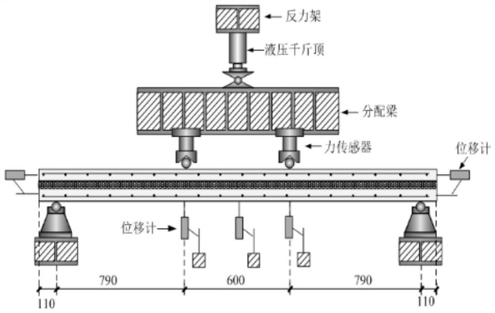
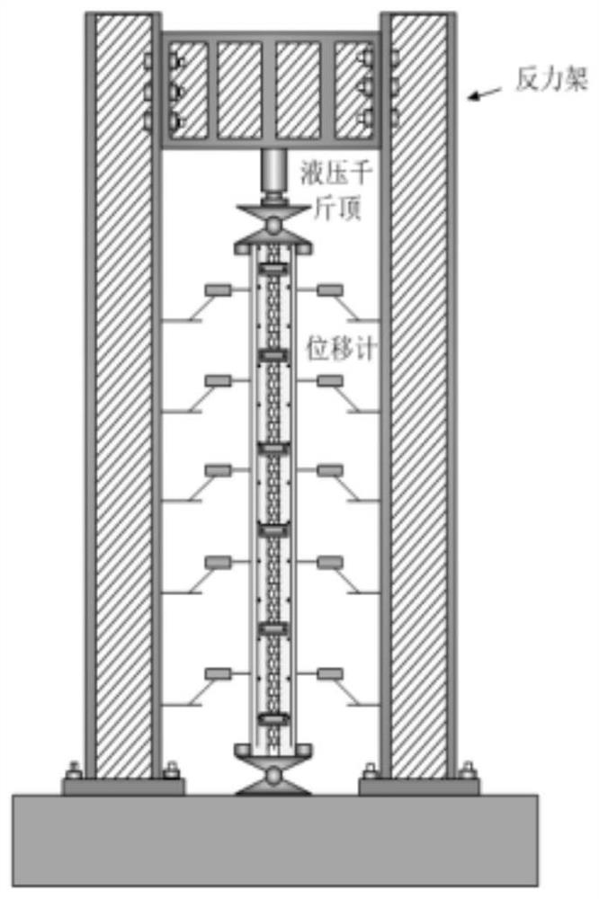

Image

  • Self-insulation composite wall body structure, installation mode, performance testing method and application of self-insulation composite wall body structure
  • Self-insulation composite wall body structure, installation mode, performance testing method and application of self-insulation composite wall body structure
  • Self-insulation composite wall body structure, installation mode, performance testing method and application of self-insulation composite wall body structure

Examples


Embodiment Construction

[0029] The following will clearly and completely describe the technical solutions in the embodiments of the present invention with reference to the accompanying drawings in the embodiments of the present invention. Obviously, the described embodiments are only some, not all, embodiments of the present invention.

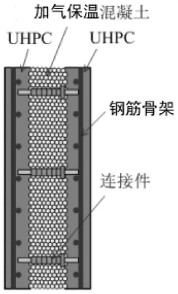
[0030] A self-insulating composite wall structure proposed by the present invention includes two layers of ultra-high-performance concrete inside and outside and aerated heat-retaining concrete in the middle layer. The aerated heat-retaining concrete is provided with a connecting piece that penetrates the two layers of the connecting piece. The ends respectively extend into the inner and outer layers of ultra-high performance concrete;

[0031] The ultra-high-performance concrete layer is provided with steel cages, and the inner layer of ultra-high-performance concrete, the aerated thermal insulation concrete layer and the outer layer of ultra-high-performance concret...


PUM

PropertyMeasurementUnit
Layer thicknessaaaaaaaaaa

Abstract

The invention discloses a self-insulation composite wall body structure. The self-insulation composite wall body structure comprises an inner ultra-high-performance concrete layer, an outer ultra-high-performance concrete layer and a middle layer of aerated insulation concrete, a penetrating connecting piece is arranged on the aerated insulation concrete, and the two ends of the connecting piece extend into the inner ultra-high-performance concrete layer and the outer ultra-high-performance concrete layer respectively; reinforcement cage skeletons are arranged in the ultra-high-performance concrete layers, and the inner ultra-high-performance concrete layer, the layer of aerated thermal insulation concrete and the outer ultra-high-performance concrete layer are built layer by layer; and the layer thickness of the inner ultra-high-performance concrete layer and the layer thickness of the outer ultra-high-performance concrete layer are both 5-10 cm, and the layer thickness of the aerated thermal insulation concrete is 10-20 cm. Compared with the prior art, the ultra-high performance concrete has higher compression resistance, shear resistance in two directions is improved compared with the traditional concrete, meanwhile, a section material has functional gradient and is a cement-based material, combination performance and anti-seismic performance are also improved, the stress mechanism of the novel wallboard is disclosed, and the excellent heat insulation and combination performance of the composite wall body structure is fully proved.

Description

technical field [0001] The invention relates to the technical field of thermal insulation composite wall machines, in particular to a self-thermal insulation composite wall structure, installation method, performance testing method and application thereof. Background technique [0002] Prefabricated buildings are buildings assembled on site with prefabricated parts and components. The General Office of the State Council's "Guiding Opinions on Vigorously Developing Prefabricated Buildings" pointed out that "the development of prefabricated buildings is a major change in the construction method, and it is an important measure to promote supply-side structural reforms and new urbanization development. It is conducive to saving resources and energy. Reducing construction pollution, improving labor production efficiency and quality and safety levels are conducive to promoting the deep integration of the construction industry and informatization industrialization, cultivating new ...

Claims


Application Information

Patent Timeline
IPC IPC(8): E04C2/04E04C2/06E04B2/00G01M13/00G01M7/02G01N3/08G01N3/20G01N3/24B28B23/00B28B23/02B28C5/00
CPCE04C2/049E04C2/06E04B2/00G01M13/00G01M7/02G01N3/08G01N3/20G01N3/24B28B23/00B28B23/02B28C5/003G01N2203/0003G01N2203/0017G01N2203/0019G01N2203/0025G01N2203/0023G01N2203/0075G01N2203/0682
Inventor 马瑞丁益
Owner ANHUI UNIVERSITY OF ARCHITECTURE
Learn More