Steering intermediate shaft angle measuring device
The technology of an angle measuring device and an intermediate shaft is applied in the field of radar parts production, which can solve the problems of cumbersome installation, inconvenient disassembly and assembly, and easy damage, and achieves the effects of improving detection efficiency, reducing detection cost, and amplifying detection results.
- Summary
- Abstract
- Description
- Claims
- Application Information
AI Technical Summary
Problems solved by technology
Method used
Image
Examples
Embodiment example 1
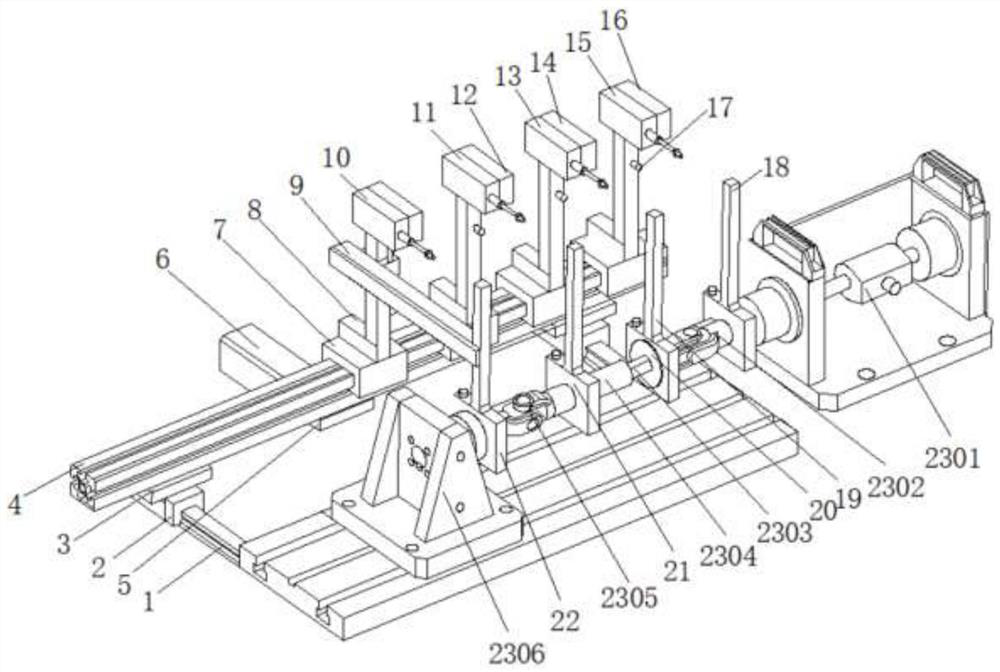
[0023] see Figure 1 to Figure 3 , the present invention provides a technical solution: steering intermediate shaft angle measuring device, including a support beam 4, and a linear guide rail 1 located at both ends of the support beam 4 and perpendicular to the central axis of the support beam 4, one end of the linear guide rail 1 is provided with a Slider 2 matching the size of linear guide rail 1, there is a backing plate 3 on the slider 2, the backing plate 3 is fixed on the support beam 4 by bolts, and four slide plates matching the size of the support beam 4 are arranged on the shaft of the support beam 4 7, and No. 4 sensor bracket 8, No. 3 sensor bracket 12, No. 2 sensor bracket 14 and No. 1 sensor bracket 16 corresponding to slide plate 7 and perpendicular to each other, and are respectively provided with No. 4 sensor bracket 8, No. 3 sensor bracket The sensor bracket 12, the No. 2 sensor bracket 14 and the No. 1 sensor bracket 16 correspond one-to-one and are fixedly ...
Embodiment example 2
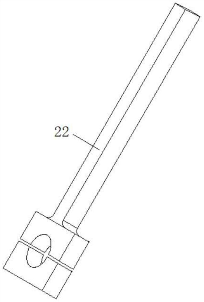
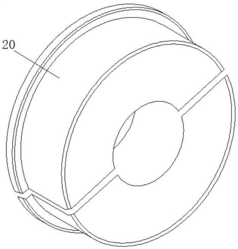
[0025] In the present invention, refer to the attached Figure 1-3 As shown, the other end of the linear guide rail 1 is provided with a slotted plate perpendicular to the linear guide rail 1, the slotted plate is provided with a steering intermediate shaft 23, and the axial direction of the steering intermediate shaft 23 is provided with a No. 1 swing arm 18 arranged in parallel, No. 2 swing arm 19, No. 3 swing arm 21 and No. 4 swing arm 22, transition sleeve 20 is provided in No. 2 swing arm 19, and steering intermediate shaft 23 includes torsion drive mechanism 2301, upper universal joint 2302, and sliding secondary spline 2303, the sliding secondary spline sleeve 2304, the lower universal joint 2305 and the fixing mechanism 2306, the output end of the torsion driving mechanism 2301 is connected with the upper universal joint 2302, and the output end of the upper universal joint 2302 is connected with the sliding secondary spline 2303, The output end of the sliding secondar...
Embodiment example 3
[0031] In the present invention, refer to the attached Figure 4 As shown, the turning and twisting drive mechanism 2301 drives the steering intermediate shaft 23 assembly to twist, the No. 1 swing arm 18, the No. 2 swing arm 19, the No. 3 swing arm 21 and the No. 4 swing arm 22 rotate with the fixed parts, and the No. 15. The detection heads of No. 2 grating displacement sensor 13, No. 3 grating displacement sensor 11 and No. 4 grating displacement sensor 10 are aligned with No. 1 swing arm 18, No. 2 swing arm 19, No. 3 swing arm 21 and No. 4 swing arm 22. Rotation in opposite directions, stretching and compressing, forming such as Figure 4 track shown.
PUM
 Abstract
Description
Claims
Application Information
 - R&D
- Intellectual Property
- Life Sciences
- Materials
- Tech Scout
- Unparalleled Data Quality
- Higher Quality Content
- 60% Fewer Hallucinations
Browse by: Latest US Patents, China's latest patents, Technical Efficacy Thesaurus, Application Domain, Technology Topic, Popular Technical Reports.
© 2025 PatSnap. All rights reserved.Legal|Privacy policy|Modern Slavery Act Transparency Statement|Sitemap|About US| Contact US: help@patsnap.com


