Fault positioning method suitable for electric power equipment

A power equipment and fault location technology, applied in the direction of constraint-based CAD, genetic rules, electrical digital data processing, etc., can solve the problems of manual judgment, reduce the accuracy and efficiency of intelligent diagnosis, and achieve the effect of high prediction accuracy

Active Publication Date: 2021-08-10
SHANGHAI JIAO TONG UNIV
View PDF4 Cites 0 Cited by
  • Summary
  • Abstract
  • Description
  • Claims
  • Application Information

AI Technical Summary

Problems solved by technology

Nowadays, fixed infrared thermal imaging probes have been popularized in various substations and other places, but the staff still need to manually judge the fault at the data receiving end, which seriously reduces the accuracy and efficiency of the entire intelligent diagnosis

Method used


Image

  • Fault positioning method suitable for electric power equipment
  • Fault positioning method suitable for electric power equipment
  • Fault positioning method suitable for electric power equipment

Examples


Embodiment 1

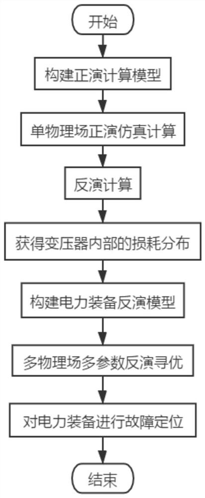
[0036] refer to figure 1 , which is the first embodiment of the present invention, this embodiment provides a fault location method suitable for electric equipment, including:

[0037] S1: Construct a forward calculation model based on the multi-physics simulation strategy, and perform forward simulation calculations for each single physical field inside the power equipment through the forward calculation model.

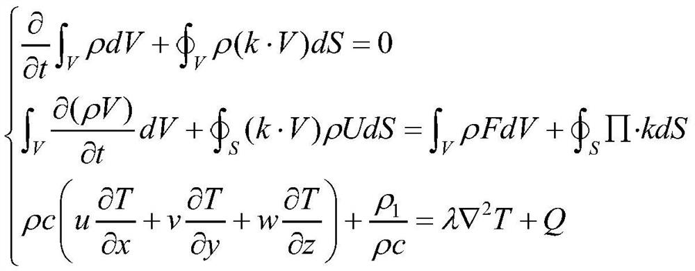
[0038]When analyzing the temperature field, it is necessary to consider the influence of various factors such as fluid, solid and heat transfer on the temperature at the same time. Based on the multi-physics simulation strategy and satisfying the law of conservation of mass, law of momentum conservation and law of energy conservation, the internal temperature field of the transformer is established. The forward calculation model of :

[0039]

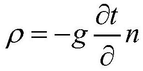
[0040] The fluid density ρ is:

[0041]

[0042] Among them, g is the thermal conductivity of the fluid, t is the su...

Embodiment 2

[0079] In order to verify and explain the technical effect adopted in this method, this embodiment chooses the traditional power equipment fault location method and adopts this method to conduct a comparative test, and compares the test results by means of scientific demonstration to verify the real effect of this method.

[0080] The traditional power equipment fault location method performs simple threshold segmentation or watershed algorithm on the infrared thermal image of power equipment to segment the hot parts. The hot parts segmented by this method often contain many non-interest region images or lose many interest region images. Seriously affect the accuracy of hot spot identification, seriously reducing the accuracy and efficiency of the entire intelligent diagnosis.

[0081] In order to verify that this method has a higher fault location accuracy than the traditional power equipment fault location method, in this embodiment, the traditional power equipment fault loca...


PUM


Abstract

The invention discloses a fault positioning method suitable for electric power equipment, and the method comprises the steps of building a forward modeling calculation model based on a multi-physical field simulation strategy, and carrying out the forward modeling simulation calculation of each single physical field in the electric power equipment through the forward modeling calculation model; performing inversion calculation according to observable data of the transformer acquired by the monitoring system to obtain loss distribution in the transformer; constructing a power equipment inversion model according to the forward modeling calculation model and the loss distribution; inputting the surface temperature of the transformer into the power equipment inversion model, and performing multi-physical field multi-parameter inversion optimization on the multi-point temperature of each component in the transformer by adopting a genetic algorithm to obtain a temperature field parameter distribution condition in the transformer; performing fault positioning on the electric power equipment according to the temperature field parameter distribution condition in the transformer. According to the invention, the fault abnormity of the power equipment can be accurately predicted in time, and an important basis is provided for operation and maintenance personnel to deal with abnormal phenomena.

Description

technical field [0001] The technical field to which the present invention relates, in particular, relates to a fault location method suitable for electric equipment. Background technique [0002] When power equipment is running, equipment heating faults caused by various reasons such as insulation aging and poor contact, such as common isolating switch heating, resistance loss heating, wire clamp heating, etc., bring major hidden dangers to the safety of power grid operation, and in serious cases cause Equipment out of operation, or even fire. Therefore, the fault detection of power equipment is one of the important topics in the research of power equipment safety. [0003] Traditional power equipment fault detection adopts the method of power outage maintenance, which is time-consuming and laborious. With the introduction of infrared thermal imaging cameras, today's thermal fault detection methods generally use infrared thermal imaging cameras to detect power equipment. C...

Claims


Application Information

Patent Timeline
Patent Type & Authority Applications(China)
IPC IPC(8): G06F30/27G06N3/00G06N3/12G06F111/04G06F113/08G06F119/08
CPCG06F30/27G06N3/006G06N3/126G06F2111/04G06F2113/08G06F2119/08
Inventor 严英杰刘亚东江秀臣
Owner SHANGHAI JIAO TONG UNIV
Why Eureka
Try Eureka