Auxiliary fixing device for carbon fiber sheet laying of railway vehicle body

A technology for a rail vehicle and a fixing device is applied in the field of auxiliary positioning devices for carbon fiber sheet paving, which can solve the problems of inability to guarantee normal lines, inability to guarantee the quality and efficiency of paving and riveting operations, time-consuming and labor-intensive, etc.

Pending Publication Date: 2021-08-13
CRRC CHANGCHUN RAILWAY VEHICLES CO LTD
View PDF0 Cites 0 Cited by
  • Summary
  • Abstract
  • Description
  • Claims
  • Application Information

AI Technical Summary

Problems solved by technology

[0006] In order to solve the existing problem of paving carbon fiber sheets on the curved surface of the car body outer wall, the larger carbon fiber sheet B often deforms and displaces to a certain extent on the streamlined surface of the outer wall A of the side wall of the car body, which makes the two unsustainable or cause some holes in the rivet hole array to be out of alignment; and the conventional bolt positioning method cannot ensure that the unloading process follows the normal line of the surface A of the outer wall of the side wall of the car body, but often causes the local area of ​​​​the carbon fiber sheet B Warping, uplift or displacement occurs in the interior, which affects the flatness of the subsequent riveting operation; the process of remedial leveling of the entire large-area carbon fiber sheet is time-consuming and laborious, and the operator cannot guarantee the quality and efficiency of paving and riveting operations. Problem, the present invention provides an auxiliary fixing device for carbon fiber sheet pavement

Method used


Image

  • Auxiliary fixing device for carbon fiber sheet laying of railway vehicle body
  • Auxiliary fixing device for carbon fiber sheet laying of railway vehicle body
  • Auxiliary fixing device for carbon fiber sheet laying of railway vehicle body

Examples


Embodiment Construction

[0040] The present invention will be further described in detail below with reference to the accompanying drawings.

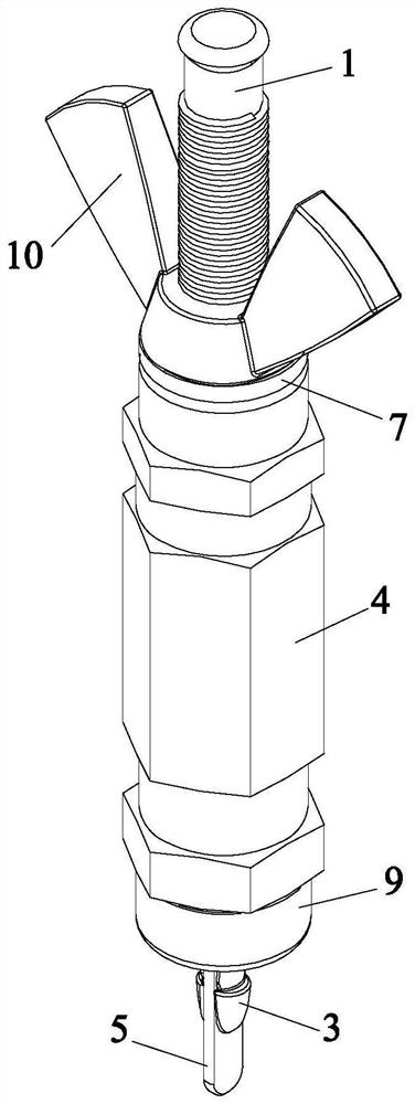
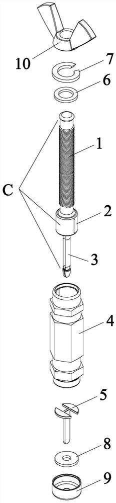
[0041] like Figures 2 to 11 As shown, the rail vehicle body carbon fiber sheet of the present invention includes auxiliary fixture including a screw 1, a guide slider 2, two single spring semi-cone 3, sleeve 4, a bullion, a sleeve end? The cover 6, the spring sheet 7, the casing 8, the sleeve front end cover 9 and the dove-tail nut 10, the screw 1 and the two-shelled cone 3 coaxial stepping on the front, rear end surface of the guide slider 2, Thin, together, form a whole cone positioning push rod C.

[0042] like Figure 5 As shown, the single spring semicircular cone 3 includes a sequential and integrally formed reed straight rod 3-1, a variable diameter elbow 3-2, and a semi-cone 3-3, two single spring sheets The cone 3 mirror symmetrical symmetry and arranges parallel and together forms a double spring cone mechanism D.

[0043] like Image 6 As shown, the bulk t...


PUM


Abstract

The invention discloses an auxiliary fixing device for carbon fiber sheet laying of a railway vehicle body, and belongs to the field of auxiliary positioning devices for carbon fiber sheet laying. The auxiliary fixing device comprises a screw rod, a guide sliding block, two single-reed type semi-conical heads, a sleeve, a tongue expanding piece, a sleeve tail end cover, a spring piece, a clamp reed, a sleeve front end cover and a dovetail type nut, wherein, the screw rod and a double-reed type conical head are coaxially and fixedly connected to the front end face and the rear end face of the guide sliding block, and the screw rod, the double-reed type conical head and the guide sliding block jointly form an integral conical head positioning push rod; and each single-reed type semi-conical head comprises a reed straight rod, a reducing elbow and a semi-conical head body which are fixedly connected in sequence and are integrally formed, and the tongue expanding piece comprises a tongue piece body and a wafer seat which are integrally formed. The device is exquisite in design, can be independently mounted and dismounted by one operator on the premise that other mounting or dismounting tools in any form are not needed, is convenient, quick, simple and practical, greatly saves the production cost, and improves the efficiency.

Description

Technical field [0001] The present invention belongs to the field of auxiliary positioning device for carbon fiber sheet, and is specifically involved in an auxiliary fixture for rail vehicle body carbon fiber sheet. Background technique [0002] Carbon fiber composites serve as a lightweight high-intensity composite material with high temperature, fatigue, and other advantages, and has been widely used in high-speed train manufacturing. [0003] like figure 1 As shown, the pavement method of the existing carbon fiber curved sheet B solids in the high-speed train flow linear vehicle body side wall A is to open a corresponding rivet hole array in the outer wall A of the carbon fiber sheet B and the vehicle body side wall A. The rivet rivet hole B-1 and the vehicle body wall plate rivet hole A-1 is achieved by riveting the rivet screw. The inside of the vehicle body wall plate rivet hole A-1 and the carbon fiber sheet B on the outer wall A of the vehicle body side wall A is D2, and...

Claims


Application Information

Patent Timeline
IPC IPC(8): B29C65/60B29C65/64B29C65/78B29L31/30
CPCB29C65/60B29C65/64B29C65/7811B29C66/45B29L2031/30
Inventor 赵强杨姝朱晓东田宇魏继光
Owner CRRC CHANGCHUN RAILWAY VEHICLES CO LTD
Why Eureka
Try Eureka