A floating coastal zone monitoring device

A monitoring device and coastal zone technology, which can be used in measurement devices, circuit devices, ship cleaning devices, etc., can solve the problems of impact monitoring, equipment rollover, single structure, etc., to ensure accuracy and efficiency, and increase contact. area, the effect of avoiding equipment power failure

Active Publication Date: 2021-10-08
山东省地质矿产勘查开发局第四地质大队
View PDF0 Cites 0 Cited by
  • Summary
  • Abstract
  • Description
  • Claims
  • Application Information

AI Technical Summary

Problems solved by technology

[0003] When monitoring the sea breeze, a water surface buoy device with an wind speed monitor installed on the upper end is usually placed on the sea for monitoring. However, the above-mentioned scheme has the following defects in use: when encountering a relatively strong sea wind The potential safety hazard of rollover not only caused damage to the equipment, but more seriously, the rollover of the equipment caused the interruption of real-time wind speed data collection on the sea surface, making it impossible to carry out follow-up analysis of natural weather and delaying the calculation of natural disasters
The existing wind speed monitor has a single structure and cannot accurately analyze the direction of the sea wind, which will cause deviations in data analysis, and if it is placed on the sea for a long time, there will be a large amount of floating objects attached to the bottom of the buoy, which will cause the equipment to be stuck on the sea surface. Floating unstable, affecting follow-up monitoring

Method used


Image

  • A floating coastal zone monitoring device
  • A floating coastal zone monitoring device
  • A floating coastal zone monitoring device

Examples


Embodiment

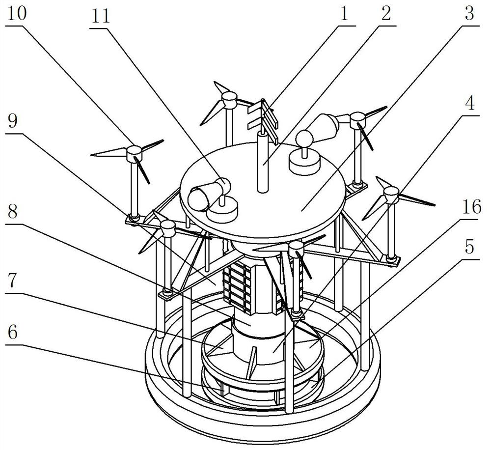
[0034] Such as Figure 1-6 As shown, a floating coastal zone monitoring device includes a chassis 8, a solar charging assembly 9 is arranged on the chassis 8, the top of the chassis 8 is fixedly connected to the first fixed sleeve 2, and the first fixed sleeve 2 is fixedly connected with a signal The transmission wire 1 is provided with an information processor 15 inside the chassis 8, the signal transmission wire 1 is electrically connected to the information processor 15, and the periphery of the first fixed sleeve 2 is fixedly installed with a mounting base 3 between the bottom of the mounting base 3 and the chassis 8 A plurality of wind speed monitoring components 10 are arranged, and the circumference of the multiple wind speed monitoring components 10 is evenly distributed on the periphery of the chassis 8. The information processor 15 is electrically connected to the wind speed monitoring components 10. The bottom of the chassis 8 is provided with a second fixed sleeve 4...


PUM


Abstract

The invention relates to a floating coastal zone monitoring device, which comprises a chassis, on which a solar charging component is arranged, the top of the chassis is fixedly connected with a first fixing sleeve, and a signal transmission wire is fixedly connected in the first fixing sleeve, and a There is an information processor, and the signal transmission wire is electrically connected to the information processor. A mounting base plate is fixedly installed on the periphery of the first fixing sleeve. A plurality of wind speed monitoring components are arranged between the bottom of the mounting base plate and the chassis. The information processor and the wind speed monitoring component Electrically connected, the bottom of the chassis is provided with a second fixed sleeve, the bottom of the second fixed sleeve is fixedly connected with a steel plate, the bottom of the steel plate is fixed with a spiked chassis, and the bottom of the chassis is provided with a floating ring. The invention ensures the accuracy and high efficiency of real-time monitoring of sea breeze, provides accurate guarantee for calculated data, avoids the hidden danger of rollover, increases the safety and practicability of equipment, and avoids the daily floating in seawater. Floating matter such as seaweed adheres to the device.

Description

technical field [0001] The invention relates to the technical field of coastal zone monitoring, in particular to a floating coastal zone monitoring device. Background technique [0002] The coastal zone refers to the zone where the sea and land interact, that is, the intertidal zone affected by the daily tide fluctuation and the sea-land transition zone between a certain range of land on both sides and the shallow sea. A large number of monitoring devices are put on the water surface to monitor the natural environment such as wind speed in the coastal zone in real time, and then analyze the daily natural environment through computer data, so as to predict natural disasters in advance. For this reason, coastal zone monitoring is the top priority. [0003] When monitoring the sea breeze, a water surface buoy device with an wind speed monitor installed on the upper end is usually placed on the sea for monitoring. However, the above-mentioned scheme has the following defects in ...

Claims


Application Information

Patent Timeline
Patent Type & Authority Patents(China)
IPC IPC(8): B63B22/00B63B22/20B63B39/00B63B43/14B63B59/06G01P5/00G01P13/02H02J7/35
CPCB63B22/00B63B22/20B63B39/005B63B43/14B63B59/06B63B2022/006B63B2043/145G01P5/00G01P13/02H02J7/35
Inventor 刘荣波金志明陈晓涛
Owner 山东省地质矿产勘查开发局第四地质大队
Why Eureka
Try Eureka