

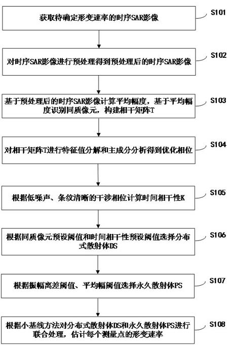
Deformation rate estimation method and system
A deformation rate and image technology, applied in radio wave measurement systems, calculations, computer components, etc., can solve problems such as unfavorable DS extraction and phase optimization, estimation bias, and covariance matrix SAR image backscatter power imbalance. , to avoid the imbalance of backscattered power, improve computing efficiency, and avoid the effect of low-quality interference phase
- Summary
- Abstract
- Description
- Claims
- Application Information
AI Technical Summary
Problems solved by technology
Method used
Image

Examples
Embodiment Construction
[0059] The principles and features of the present invention are described below in conjunction with the accompanying drawings, and the examples given are only used to explain the present invention, and are not intended to limit the scope of the present invention.
[0060] In order to better understand the above-mentioned purpose, features and advantages of the present application, the present disclosure will be further described in detail below in conjunction with the accompanying drawings and embodiments. It should be understood that the described embodiments are some of the embodiments of the present disclosure, but not all of the embodiments. The specific embodiments described here are only used to explain the present disclosure, but not to limit the present application. All other embodiments obtained by persons of ordinary skill in the art based on the described embodiments of the present application belong to the protection scope of the present application.
[0061] fig...
PUM
 Abstract
Description
Claims
Application Information