membrane switch

A technology of membrane switch and relationship, which is applied in the field of electric switches, can solve the problems of corrosion of conductors, poor comfort in use, poor contact, etc., and achieve the effects of avoiding oxidation and corrosion, good pressing comfort, and short connection distance

Active Publication Date: 2021-10-01
KUNSHAN JOING TECH
View PDF1 Cites 0 Cited by
  • Summary
  • Abstract
  • Description
  • Claims
  • Application Information

AI Technical Summary

Problems solved by technology

[0004] 1. The pressing air cavity is connected to the airway. When the airway is compressed, the air pressure in the pressing air cavity will increase, and a large force is required to press the substrate to realize the compression of the pressing air cavity, and the use comfort is poor;
[0005] 2. Once the water enters the pressing air cavity through the air passage, it is difficult to discharge, and it is easy to corrode the conductor in the pressing air cavity, resulting in poor contact, and in severe cases, it will also lead to permanent failure of the membrane switch function

Method used


Image

  • membrane switch
  • membrane switch
  • membrane switch

Examples


Embodiment 1

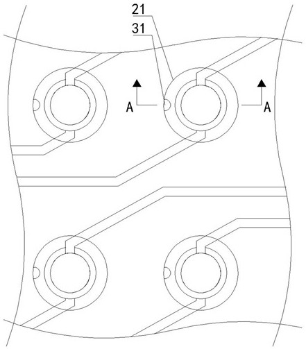
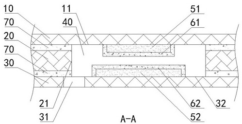
[0029] like Figure 1-2 As shown, the membrane switch provided by the present invention includes an upper substrate 10, a partition 20 and a lower substrate 30 arranged sequentially from top to bottom. The upper substrate 10 and the lower substrate 30 are both flexible thin film plates. The first through hole passing through the partition plate 20 in the up and down direction, the cross section of the first through hole is circular, surrounded by the hole wall 21 of the first through hole, the lower surface 11 of the upper substrate 10, and the upper surface 32 of the lower substrate 30. The formed cavity forms a pressing air chamber 40, and a conductor is arranged in the pressing air chamber 40, and the conductor includes an upper conductor 51 arranged on the lower surface 11 of the upper substrate 10 and a lower conductor 52 arranged on the upper surface 32 of the lower substrate 30, The spacer 20 is airtightly connected with the upper substrate 10 and the lower substrate 30...

Embodiment 2

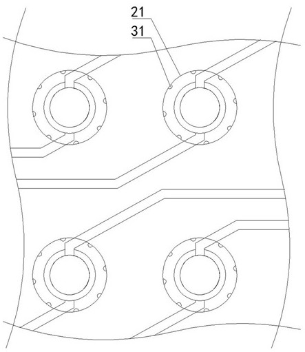
[0035] like image 3 As shown, the second embodiment is substantially the same as the first embodiment, the difference is that in the second embodiment, there are eight second through holes 31 communicating with a single pressing air chamber 40, and the eight second through holes 31 use the first The through-holes are distributed in a circular array with the axis line as the center. The advantage of this arrangement is that it can further reduce the impact on the strength of the lower substrate 30 under the premise of ensuring the communication area. When pressing, it can also press the air cavity 40 in a balanced manner. local air pressure to avoid the phenomenon that the upper substrate 10 is skewed due to the increase of local air pressure.

[0036] The membrane switch provided by the present invention adopts the idea of ​​reducing the difficulty of water entering and leaving the pressing air cavity when water enters the pressing air cavity, and avoids the oxidation and cor...


PUM


Abstract

The membrane switch provided by the present invention comprises an upper substrate, a partition and a lower substrate which are sequentially arranged from top to bottom. The cavity enclosed between the surface and the upper surface of the lower substrate forms a pressing air cavity, and a conductor is arranged inside the pressing air cavity, and the conductor is arranged on the surface of the opposite side of the upper and lower substrates. A second through hole connecting the pressing air cavity and the outside world is opened on the lower substrate, an isolation layer is set on the outer wall of the conductor, and the conduction of the upper and lower conductors is realized through the mutual contact of the isolation layer, so that the pressing air cavity is connected to the outside world. They are only connected through the second through hole, the connection distance is short, the efficiency of drainage and exhaust is high, the pressing comfort is good, the drainage is good, and the conductor can be isolated from the air and water in the pressing air cavity through the isolation layer to avoid Oxidation and corrosion of conductors achieve the technical effect of restoring the original function after the water is discharged.

Description

technical field [0001] The invention relates to the technical field of electric switches, in particular to a membrane switch. Background technique [0002] Membrane switch is a new type of electronic switch, which is used to control the on-off of the circuit where it is located. It is widely used in the assembly of various key panels, computer keyboards and other products. Most of the existing membrane switches include: upper and lower substrates, formed between the upper and lower substrates The pressing air chamber, the conductor located in the pressing air chamber and arranged on the surface of the upper and lower substrates opposite to each other, when the membrane switch is pressed, the upper and lower substrates are deformed, and the pressing air chamber is compressed, so that the conductor is connected to the circuit where the membrane switch is located, realizing signal output. [0003] For this type of membrane switch, in order to achieve compression and rebound of...

Claims


Application Information

Patent Timeline
Patent Type & Authority Patents(China)
IPC IPC(8): H01H13/703H01H13/704H01H13/06
CPCH01H13/06H01H13/703H01H13/704
Inventor 丁秀琴张勰军卢俊生吴磊黄三明
Owner KUNSHAN JOING TECH
Why Eureka
Try Eureka