Power battery compatible platform and electric vehicle

A power battery and battery technology, applied in the direction of electric vehicles, battery/battery traction, batteries, etc., can solve the problems of pure electric vehicles on the same level, unsolved charging time, shortening the research and development cycle, etc., to achieve thermal management Structural consistency, shortening the R&D cycle, and the effect of shortening the development cycle

Pending Publication Date: 2021-08-17
CHINA FIRST AUTOMOBILE
19 Cites 0 Cited by

AI-Extracted Technical Summary

Problems solved by technology

[0003] The choice restrictions brought to users by the existing planned electric vehicle platform are mainly reflected in the mileage and price. Although the platform concept of platform modularization saves a lot of development costs and shortens the research and development cycle, it also solidifies the The basic characteristics of the electric vehicles produced by the platform have no...

Method used

Other platform parts except power battery are through the development of platform, can guarantee to change outfit with minimum cost when facing diversified power battery assembly, reduce development amount to the greatest extent and shorten development period, save development cost. Through the modularization of the power battery system, while meeting the needs of customization, the differentiation is eliminated to the greatest extent, ensuring the maximum universalization of parts and production line fixtures, which not only saves production costs but also shortens R&D. cycle.
The placement position of the front end can ensure that the front end faces of all power batteries are arranged in the same position, the first fixed point 01 and the second fixed point 02 fix the charging version of the battery, and the third fixed point 03 fixes the first battery replacement version The battery, the third fixed point 03 and the fourth fixed point 04 fix the second replacement battery, which can make the power battery compatible platform compatible with different types of power batteries; the high-voltage interface on the power battery is compatible with the high-voltage power distribution box connected to realize the charging and discharging of the power battery, which can realize the unification of the high-voltage topology of the power battery compatible platform; the battery thermal management circuit 20 realizes heat exchange with the heating system 10 through the first heat exchanger 4a, so that the heating system 10 is The power battery is heated; the battery heat management circuit 20 realizes heat exchange with the air conditioner heat management circuit 30 through the second heat exchanger 8a, so that the air conditioner heat management circuit 30 cools the power battery; at the same time, the heating system 10 and the air conditioner heat The management circuit 30 can also act on the passenger compartment 3a of the whole vehicle; it can realize the consistency of the thermal management structure of the power battery, and can meet the thermal management requirements of different power batteries.
[0051] The high-voltage topology includes the high-voltage power distribution box of the vehicle's high-voltage system. The power battery is provided with a high-volt...

Abstract

The invention relates to the technical field of power battery mounting platforms, and discloses a power battery compatible platform and an electric vehicle. The platform comprises: a front end face placing position used for placing the front end face of a power battery; a vehicle body floor which comprises a floor body and threshold beams arranged on the two sides of the floor body, wherein the floor body is provided with a plurality of first fixing point positions, and the threshold beams are provided with a plurality of second fixing point positions; a plurality of third fixing point positions and a plurality of fourth fixing point positions; a high-voltage topological structure which comprises a high-voltage distribution box, wherein the power battery is provided with a high-voltage interface, and the high-voltage interface is connected with the high-voltage distribution box; and a heat management system which comprises a heating system, a battery heat management loop and an air conditioner heat management loop, wherein the heating system is coupled with the battery heat management loop through a first heat exchanger, the heating system achieves coupling switching with a passenger compartment and the battery heat management loop through a three-way valve, the battery heat management loop is coupled with the air conditioner heat management loop through a second heat exchanger, and the air conditioner heat management loop can also be coupled with the passenger compartment.

Application Domain

Air-treating devicesElectric propulsion mounting +7

Technology Topic

Automotive engineeringElectrical battery +7

Image

  • Power battery compatible platform and electric vehicle
  • Power battery compatible platform and electric vehicle

Examples

  • Experimental program(1)

Example Embodiment

[0032] In order to make the purposes, technical solutions and advantages of the embodiments of the present invention clearer, the technical solutions in the embodiments of the present invention will be clearly and completely described below with reference to the accompanying drawings in the embodiments of the present invention. Obviously, the described embodiments These are some embodiments of the present invention, but not all embodiments. The components of the embodiments of the invention generally described and illustrated in the drawings herein may be arranged and designed in a variety of different configurations.
[0033] Thus, the following detailed description of the embodiments of the invention provided in the accompanying drawings are not intended to limit the scope of the invention as claimed, but are merely representative of selected embodiments of the invention. Based on the embodiments of the present invention, all other embodiments obtained by those of ordinary skill in the art without creative efforts shall fall within the protection scope of the present invention.
[0034] It should be noted that like numerals and letters refer to like items in the following figures, so once an item is defined in one figure, it does not require further definition and explanation in subsequent figures.
[0035] In the description of the present invention, it should be noted that the terms "upper", "lower", "left", "right", "vertical", "horizontal", "inner", "outer", etc. indicate the orientation or The positional relationship is based on the orientation or positional relationship shown in the accompanying drawings, or the orientation or positional relationship that the product of the invention is usually placed when it is used. It is only for the convenience of describing the present invention and simplifying the description, rather than indicating or implying the device referred to. Or elements must have a particular orientation, be constructed and operate in a particular orientation, and therefore should not be construed as limiting the invention. Furthermore, the terms "first", "second", "third", etc. are only used to differentiate the description and should not be construed as indicating or implying relative importance. In the description of the present invention, unless otherwise specified, "plurality" means two or more.
[0036] In the description of the present invention, it should also be noted that, unless otherwise expressly specified and limited, the terms "arrangement" and "connection" should be understood in a broad sense, for example, it may be a fixed connection or a detachable connection, or Integrally connected; either mechanical or electrical. For those of ordinary skill in the art, the specific meanings of the above terms in the present invention can be understood in specific situations.
[0037]In the present invention, unless otherwise expressly specified and limited, a first feature "on" or "under" a second feature may include the first and second features in direct contact, or may include the first and second features Not directly but through additional features between them. Also, the first feature being "above", "over" and "above" the second feature includes the first feature being directly above and obliquely above the second feature, or simply means that the first feature is level higher than the second feature. The first feature is "below", "below" and "below" the second feature includes the first feature being directly below and diagonally below the second feature, or simply means that the first feature has a lower level than the second feature.
[0038] The following describes in detail the embodiments of the present invention, examples of which are illustrated in the accompanying drawings, wherein the same or similar reference numerals refer to the same or similar elements or elements having the same or similar functions throughout. The embodiments described below with reference to the accompanying drawings are exemplary, only used to explain the present invention, and should not be construed as a limitation of the present invention.
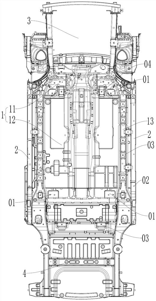
[0039] like figure 1 As shown, this embodiment discloses a power battery compatible platform, which includes a front end face placement position, a vehicle body floor, a high voltage topology and a thermal management system.
[0040] The power battery includes a rechargeable version battery, a first battery replacement version and a second battery replacement version. The front-end surface placement position is set on the vehicle body floor, and is used to place the front-end surface of the rechargeable battery, the first battery-changing version or the second battery-changing version, so that the front-end surfaces of all power batteries are arranged in the same position. The power of the same-boundary power battery can also be expanded by replacing cells with different power levels, rather than by changing the structural size.
[0041] The vehicle body floor includes a floor body 1 and rocker beams 2 arranged on both sides of the floor body 1. The floor body 1 is provided with a plurality of first fixing points 01 for fixing the front and rear ends of the rechargeable battery. The rocker beam 2 is provided with A plurality of second fixing points 02 are used to fix the left and right sides of the rechargeable battery; the floor body 1 is also provided with a plurality of third fixing points 03 and a plurality of fourth fixing points 04. The third fixing point 03 is used to fix the battery of the first replacement version and the second battery of the replacement version, and the fourth fixing point 04 is used to fix the battery of the second replacement version.
[0042] Specifically, the vehicle body floor also includes a front suspension 3 connected to the front end of the floor body 1 and a rear suspension 4 connected to the rear end of the floor body 1 , wherein the front suspension 3 is a McPherson suspension, and the rear suspension 4 is Torsional beam suspension, the entire platform suspension has a unified hard point, the disk distance can be changed if there is a need to expand the vehicle width, and it can be strengthened if there is a need to expand the bearing capacity.
[0043] The rechargeable battery is specifically a long-life and normal-life rechargeable ternary lithium battery or a long-life and normal-life rechargeable lithium iron phosphate battery. The battery of the second battery is the ternary lithium battery of the battery with high life and ordinary life.
[0044] The floor body 1 includes a front floor 11 and a middle and rear floor 12 disposed behind the front floor 11 . Part of the first fixing point 01 is arranged on the front floor 11 for fixing the front end of the rechargeable battery; another part is arranged on the middle and rear floor 12 for fixing the rear end of the rechargeable battery. More specifically, two first fixing points 01 are provided at intervals along the width direction of the entire vehicle on the front floor 11, and the front end of the rechargeable battery is fixed here. Two first fixing points 01 are provided at the position of the middle and rear floor 12 close to the rear suspension 4 . The two first fixing points 01 are arranged at intervals along the width direction of the vehicle, and the rear end of the rechargeable battery is fixed here.
[0045] The rocker beam 2 is provided with four second fixing points 02 at intervals. The two rocker beams 2 provide a total of eight second fixing points 02. The side of the rechargeable battery is fixed on the second fixing point 02 of the rocker beam 2. superior. Four first fixing points 01 and eight second fixing points 02 can fix the front and rear ends and the left and right sides of the rechargeable battery on the body floor.
[0046] The third fixing point 03 and the fourth fixing point 04 are both nut boxes. Part of the third fixing point 03 is set on the middle and rear floor 12 for fixing the rear ends of the first battery and the second battery. Specifically, there are two third fixing points on the middle and rear floor 12 Position 03, two third fixing points 03 are arranged at intervals along the vehicle width direction. These two third fixing points 03 are located behind the two first fixing points 01 on the middle and rear floor 12. The rear ends of the first battery and the second battery are fixed here.
[0047] The floor body 1 is provided with two installation longitudinal beams 13, the installation longitudinal beams 13 are located near the edge of the floor body 1, and are located on the inner side of the rocker beam 2, and part of the third fixed point 03 is set on the installation longitudinal beam 13. On the side where the first replacement battery and the second replacement battery are fixed. Six third fixing points 03 are arranged on the mounting longitudinal beam 13 at intervals along its length direction, and the side edges of the first battery and the second battery are fixed here by bolts.
[0048] The third fixing point 03 on the middle and rear floor 12 and the third fixing point 03 on the two mounting longitudinal beams 13 fix the rear end and the left and right sides of the first battery of the battery to be replaced. The installation is fixed, the front end of the first battery replacement version does not need to be fixed.
[0049] The fourth fixed point 04 is arranged on the front side of the floor body 1, and there are two fourth fixed points 04. The fourth fixed point 04 and the two first fixed points 01 on the front floor 11 are in the length direction of the vehicle. at the same location above. The two fourth fixing points 04 are located between the two first fixing points 01 on the front floor 11 in the width direction of the whole vehicle, and the front end of the second battery is fixed here by bolts.
[0050] The third fixing point 03 on the middle and rear floor 12 and the third fixing point 03 on the two mounting longitudinal beams 13 fix the rear end and the left and right sides of the second battery Four fixing points 04 fix the front end of the battery of the second power exchange version to complete the installation and fixation of the second power exchange version of the battery.
[0051] The high-voltage topology structure includes the high-voltage distribution box of the high-voltage system of the whole vehicle. The power battery is provided with a high-voltage interface. The high-voltage interface is connected to the high-voltage distribution box. The high-voltage interface is used for charging and discharging the power battery. Only the main positive, main negative and pre-charge relays are retained in the rechargeable battery, the first battery replacement version and the second battery replacement version, which are separated from the charging system, and the high-voltage interface takes both charging and discharging functions. The high-voltage system of the whole vehicle can be connected to the high-voltage interface through the high-voltage distribution box in the engine room as the only interface. That is, by simplifying the high-voltage connection between the power battery and the whole vehicle, all types of power batteries are unified into the same high-voltage topology, so as to realize the unification of the high-voltage topology of the whole platform.
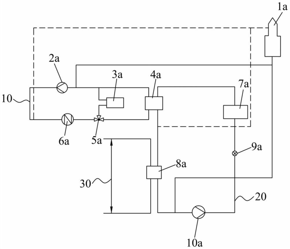
[0052] like figure 2 As shown, the thermal management system includes a heating system 10, a battery thermal management circuit 20, an air conditioning thermal management circuit 30, a first heat exchanger 4a, a second heat exchanger 8a and an expansion water tank 1a. The expansion tank 1a maintains the pressure of each circuit, and supplies heat transfer fluid to the corresponding circuit when the heat transfer fluid is consumed more, so as to ensure the heat management efficiency of the circuit. The heating system 10 includes a series connected first water pump 2a, a plumbing PTC 6a and a three-way valve 5a. The first water pump 2a drives the flow of heat transfer fluid within the heating system 10 . The plumbing PTC 6a heats the heat transfer fluid within the heating system 10 . The heating system 10 is coupled or disconnected from the thermal management circuit of the passenger compartment 3a via the three-way valve 5a. The heating system 10 is connected in parallel with the battery thermal management circuit 20 through the first heat exchanger 4a to heat the heat transfer fluid in the battery thermal management circuit 20 . The battery thermal management circuit 20 includes a power battery 7a connected in series, a second water pump 10a and a temperature sensor 9a. The second water pump 10a is used to drive the flow of heat transfer fluid in the thermal battery thermal management loop 20 . The temperature sensor 9a is used to detect the temperature of the heat transfer fluid in the battery thermal management circuit 20 in real time, so as to adjust the power of the plumbing PTC 6a and the opening degree of the first heat exchanger 4a in real time. The plumbing PTC is a controllable electric heater. When heating, the heat transfer fluid in the heating system 10 is heated first, and the heat transfer fluid in the battery thermal management circuit 20 is heated through the first heat exchanger 4a. The heating system 10 can also act on the passenger compartment 3a of the entire vehicle, and the three-way valve 5a is controlled by software to switch the heating supply between the passenger compartment 3a and the power battery.
[0053] The air conditioning thermal management circuit 30 cools down the battery thermal management circuit 20 through the second heat exchanger 8a, and the air conditioning thermal management circuit 30 can also act on the passenger compartment 3a of the entire vehicle. In order to realize that all power batteries of the whole platform share the same thermal management system, the maximum cooling capacity of the air-conditioning thermal management circuit 30 can meet the cooling requirements of all power batteries while satisfying the passenger compartment 3a, which is integrated in the second heat exchanger 8a through control. The opening degree of the adjustable electronic expansion valve can adjust the cooling demand of different batteries, so as to realize the unification of the battery cooling system hardware, and the differentiation of the cooling demand of different batteries is through the software to open and close the threshold of the battery cooling demand. It is realized by the differentiated configuration of the software and the differentiated control strategy of the opening degree of the electronic expansion valve. Similarly, for the heating system, the hardware is unified, and the differentiated needs of different batteries are realized through the differentiated heating control strategy of the controller software.
[0054] The front-end face placement position can ensure that the front-end faces of all power batteries are arranged in the same position. The first fixed point 01 and the second fixed point 02 fix the rechargeable battery, the third fixed point 03 fixes the first power-changing battery, and the first fixed point 03. The third fixed point 03 and the fourth fixed point 04 fix the second battery of the power battery, which can make the power battery compatible platform compatible with the installation of different types of power batteries; the high voltage interface on the power battery is connected with the high voltage distribution box to realize The charging and discharging of the power battery can realize the unification of the high-voltage topology of the power battery compatible platform; the battery thermal management circuit 20 realizes heat exchange with the heating system 10 through the first heat exchanger 4a, so that the heating system 10 can heat the power battery. ; The battery thermal management loop 20 realizes heat exchange with the air conditioning thermal management loop 30 through the second heat exchanger 8a, so that the air conditioning thermal management loop 30 cools the power battery; at the same time, the heating system 10 and the air conditioning thermal management loop 30 It can also act on the passenger compartment 3a of the whole vehicle; it can achieve the consistency of the thermal management structure of the power battery, and can meet the thermal management requirements of different power batteries.
[0055] Except for the power battery, the platform-based development of the other platform parts can ensure the replacement at the least cost when facing a variety of power battery assemblies, minimize the amount of development, shorten the development cycle, and save development costs. Through the modularization of the power battery system, the differentiation can be removed to the greatest extent while meeting the needs of customization, ensuring the maximum generalization of components and the maximum generalization of production line fixtures, which not only saves production costs but also shortens research and development. cycle.
[0056] This embodiment also discloses an electric vehicle, which includes the above-mentioned power battery compatible platform.
[0057] Obviously, the above-mentioned embodiments of the present invention are only examples for clearly illustrating the present invention, rather than limiting the embodiments of the present invention. For those of ordinary skill in the art, changes or modifications in other different forms can also be made on the basis of the above description. There is no need and cannot be exhaustive of all implementations here. Any modifications, equivalent replacements and improvements made within the spirit and principle of the present invention shall be included within the protection scope of the claims of the present invention.

PUM

no PUM

Description & Claims & Application Information

We can also present the details of the Description, Claims and Application information to help users get a comprehensive understanding of the technical details of the patent, such as background art, summary of invention, brief description of drawings, description of embodiments, and other original content. On the other hand, users can also determine the specific scope of protection of the technology through the list of claims; as well as understand the changes in the life cycle of the technology with the presentation of the patent timeline. Login to view more.

Similar technology patents

Hall type pedal location sensor and brake pedal device

InactiveCN106740753AReduce tooling developmentReduce the amount of development
Owner:CHERY AUTOMOBILE CO LTD

Navigation bar configuration method and device, computer equipment and storage medium

PendingCN110175301AStrong scalabilityReduce the amount of development
Owner:PING AN TECH (SHENZHEN) CO LTD

Data pushing method and device, storage medium and computer equipment

InactiveCN110460659AImprove efficiencyReduce the amount of development
Owner:辽宁途隆科技有限公司

Data lake-based data management system and method

PendingCN112307122AReduce the amount of developmentreduce complexity
Owner:HANGZHOU HIKVISION DIGITAL TECH
Why Eureka
Try Eureka