Loom equipment with broken yarn recognition function

A technology of broken yarn identification and loom, which is applied in looms, textiles, textiles and papermaking, etc., to achieve the effects of short loom preparation time, easy positioning, and simple structure

Pending Publication Date: 2021-08-17
PICANOL SUZHOU IND PARK TEXTILE MACHINERY
View PDF0 Cites 0 Cited by
  • Summary
  • Abstract
  • Description
  • Claims
  • Application Information

AI Technical Summary

Problems solved by technology

[0004] The purpose of the present invention is to solve the problems existing in the existing warp stopping device, and no longer use the judgment of each warp yarn to detect whether the warp yarn is broken or loose, thereby greatly simplifying the machine preparation and the operation process after the warp yarn is broken

Method used


Image

  • Loom equipment with broken yarn recognition function
  • Loom equipment with broken yarn recognition function
  • Loom equipment with broken yarn recognition function

Examples


Embodiment

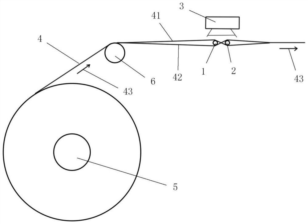
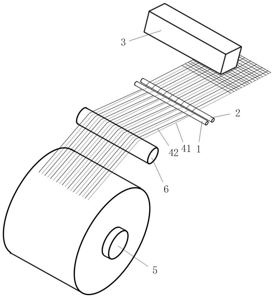
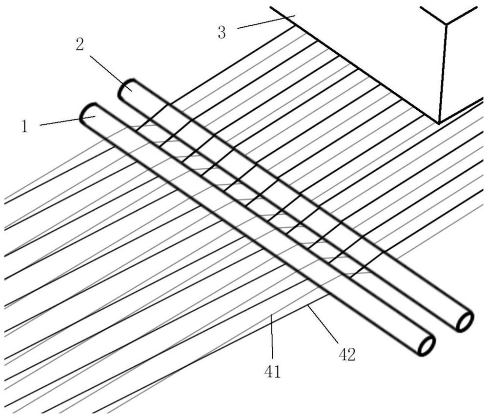
[0024] see Figure 1 to Figure 6 , figure 1 A schematic diagram of the side view structure of the loom equipment with broken yarn recognition provided in the embodiment of the present application; figure 2 A schematic diagram of the three-dimensional structure of the loom equipment with broken yarn recognition provided in the embodiment of the present application; image 3 A schematic diagram of the partial structure of the loom equipment with broken yarn recognition provided in the embodiment of the present application at the position of the two yarn dividing rollers; Figure 4 Schematic diagram of images captured by the image recognition device for loom equipment with broken yarn recognition provided in the embodiment of the present application; Figure 5 A schematic diagram of the image captured by the image recognition device when a warp yarn breaks in the loom equipment with broken yarn recognition provided in the embodiment of the present application; Image 6 It is ...


PUM


Abstract

The invention discloses loom equipment with a broken yarn recognition function. The loom equipment comprises a first yarn splitting roller, a second yarn splitting roller, an image recognition device and a plurality of warps; the first yarn splitting roller and the second yarn splitting roller are the same in axial direction, and the first yarn splitting roller and the second yarn splitting roller are adjacent and are arranged at intervals; a plurality of warps are sequentially distributed in the length direction of the first yarn splitting roller or the length direction of the second yarn splitting roller; the length direction of the warps is perpendicular to the length direction of the yarn splitting rollers; the warps penetrate through the space between the first yarn splitting roller and the second yarn splitting roller; one end of each warp extends in the direction, away from the second yarn splitting roller, of the first yarn splitting roller, and the other end of each warp extends in the direction, away from the first yarn splitting roller, of the second yarn splitting roller; and the working direction of the image recognition device faces the first yarn splitting roller and the second yarn splitting roller. According to the loom equipment, whether the warp is broken or loosened or not is not detected by judging each warp any more, so that the preparation before starting the loom and the operation process after the warp is broken are greatly simplified.

Description

technical field [0001] The invention relates to the technical field of textile equipment, in particular to a loom equipment with broken yarn identification. Background technique [0002] During the operation of the loom, weaving products are formed by the interweaving of warp and weft yarns. The warp yarn must maintain a constant tension during the operation of the loom, so it is necessary to detect the tension change of each warp yarn at all times. The operation of the menopause detection device of the common loom configuration is too complex at present, and each warp yarn must pass through a warp stopper, and the height of the warp stopper is used to judge whether the warp ends are broken or slack. Usually, each loom has a number of warp yarns ranging from thousands to tens of thousands, and correspondingly, a corresponding number of warp droppers is required. This device wastes considerable time in the preparation process of the loom, and in the operation of handling th...

Claims


Application Information

Patent Timeline
Patent Type & Authority Applications(China)
IPC IPC(8): D03D51/28
CPCD03D51/28
Inventor 殷鑫
Owner PICANOL SUZHOU IND PARK TEXTILE MACHINERY
Why Eureka
Try Eureka