Photoelectric detector structure and preparation method thereof

A technology of photodetectors and electrodes, which is applied in the direction of circuits, electrical components, semiconductor devices, etc., can solve problems such as complex manufacturing processes, and achieve the effects of enhancing optical reflection, improving device reliability, and high responsiveness

Pending Publication Date: 2021-08-17
GUANGDONG GREATER BAY AREA INST OF INTEGRATED CIRCUIT & SYST
View PDF4 Cites 0 Cited by
  • Summary
  • Abstract
  • Description
  • Claims
  • Application Information

AI Technical Summary

Problems solved by technology

There are also a few detectors with a resonant cavity structure, but they usually use fine and complex Bragg mirrors, and the manufacturing process is also very complicated

Method used


Image

  • Photoelectric detector structure and preparation method thereof
  • Photoelectric detector structure and preparation method thereof
  • Photoelectric detector structure and preparation method thereof

Examples


Embodiment Construction

[0032] Hereinafter, embodiments of the present disclosure will be described with reference to the drawings. It should be understood, however, that these descriptions are exemplary only, and are not intended to limit the scope of the present disclosure. Also, in the following description, descriptions of well-known structures and techniques are omitted to avoid unnecessarily obscuring the concepts of the present disclosure.

[0033] Various structural schematic diagrams according to embodiments of the present disclosure are shown in the accompanying drawings. The figures are not drawn to scale, with certain details exaggerated and possibly omitted for clarity of presentation. The shapes of the various regions and layers shown in the figure, as well as their relative sizes and positional relationships are only exemplary, and may deviate due to manufacturing tolerances or technical limitations in practice, and those skilled in the art will Regions / layers with different shapes, ...


PUM

PropertyMeasurementUnit
thicknessaaaaaaaaaa
thicknessaaaaaaaaaa

Abstract

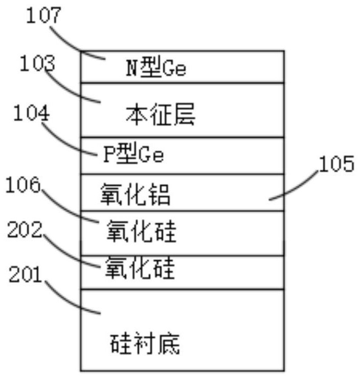
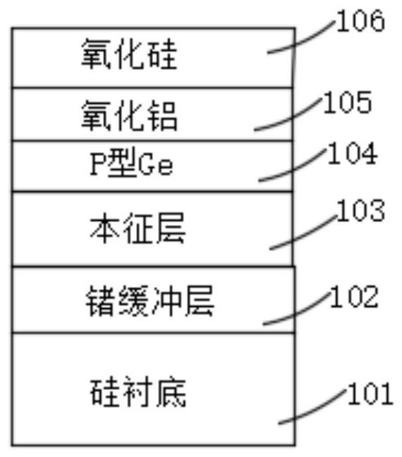
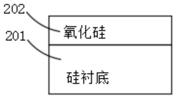
The invention relates to the field of semiconductor production, in particular to a photoelectric detector structure and a preparation method thereof. The photoelectric detector structure comprises a substrate, a first silicon oxide layer, a second silicon oxide layer, an aluminum oxide layer and a P-I-N stacking layer, wherein the thickness of the second silicon oxide layer is 10nm-1 [mu]m. The preparation method comprises the following steps: forming the germanium buffer layer on the substrate; forming an intrinsic semiconductor layer; forming a P-type semiconductor layer; forming an aluminum oxide layer, forming or not forming a second silicon dioxide layer, and obtaining a substrate A, wherein the thickness of the second silicon dioxide layer is 10 nm to 1 [mu]m; forming a first silicon oxide layer on the other substrate, and if the substrate A does not form the second silicon oxide layer, continuing to form the second silicon oxide layer to obtain a substrate B; bonding the substrate A and the substrate B; removing the substrate and the germanium buffer layer in the A substrate; and forming an N type semiconductor layer. The thicker double-layer silicon oxide structure is arranged below the PIN stacking structure, so that internal optical reflection of the device is enhanced, an optical resonant cavity is formed in the device, and the effect of the optical resonant cavity is enhanced.

Description

technical field [0001] The invention relates to the field of semiconductor production, in particular to a photodetector structure and a preparation method thereof. Background technique [0002] High-performance photodetectors are the core equipment connecting optical devices and electronic devices. Their excellent photoelectric performance provides a solid foundation for efficient conversion and transmission of photoelectric signals and accurate reading of information, and provides a solid foundation for photoelectric integrated chip technology solutions. Core equipment support. [0003] Most of the traditional PIN detector structure has no optical resonance enhancement effect inside, and its responsivity needs to be improved. There are also a few detectors with a resonant cavity structure, but they usually use fine and complex Bragg mirrors, and the manufacturing process is also very complicated. [0004] For this reason, the present invention is proposed. Contents of t...

Claims


Application Information

Patent Timeline
Patent Type & Authority Applications(China)
IPC IPC(8): H01L31/0216H01L31/105H01L31/18
CPCH01L31/02161H01L31/105H01L31/1808Y02P70/50
Inventor 亨利·H·阿达姆松赵雪薇王桂磊罗雪
Owner GUANGDONG GREATER BAY AREA INST OF INTEGRATED CIRCUIT & SYST
Why Eureka
Try Eureka