A kind of electrolytic copper foil manufacturing and processing equipment

A technology for electrolytic copper foil and processing equipment, applied in the field of electrolytic copper foil manufacturing and processing equipment, can solve the problems of inability to wipe dry water stains, poor effect of absorbing water stains, and poor cleaning effect of copper foil, etc., so as to facilitate adsorption and removal , to avoid the effect of poor cleaning effect

Active Publication Date: 2021-10-01
SHENZHEN GOLF & FEIHUANG TECH
View PDF6 Cites 0 Cited by
  • Summary
  • Abstract
  • Description
  • Claims
  • Application Information

AI Technical Summary

Problems solved by technology

[0002] Electrolytic copper foil refers to the use of electrolytic copper or wire return materials of the same purity as raw materials, dissolved in a solution containing copper sulfate, and a cathode roll that uses insoluble materials as an anode and is dipped in copper sulfate electrolyte at a constant speed at the bottom. Electrolysis is carried out in the electrolytic cell of the cathode, and the copper in the solution is deposited on the surface of the cathode roller to form copper foil. The thickness of the copper foil is controlled by the cathode current density and the speed of the cathode roller. , and then continuously stripped from the cathode roll, the surface of the stripped copper foil may have residual impurities, so it needs to be cleaned and removed. The following problems will occur in the process of cleaning and drying the copper foil: 1. There may be more impurities attached to the copper foil during the peeling process. At present, the cleaning of the copper foil is mostly done by cleaning the copper foil with a cleaning roller. The contact area between the cleaning roller and the copper foil surface is small, resulting in poor cleaning effect of the copper foil
[0003] 2. When drying the copper foil, the sponge is often used to directly dry the water stains on the surface of the copper foil. When the sponge is wiped for a certain period of time, there will be a certain amount of water stains inside the sponge, thus As a result, when the sponge wipes the copper foil behind it, the effect of absorbing water stains is not good, and the water stains on the copper foil cannot be wiped dry

Method used


Image

  • A kind of electrolytic copper foil manufacturing and processing equipment
  • A kind of electrolytic copper foil manufacturing and processing equipment
  • A kind of electrolytic copper foil manufacturing and processing equipment

Examples


Embodiment Construction

[0025] The embodiments of the present invention will be described in detail below with reference to the accompanying drawings, but the present invention can be implemented in many different ways defined and covered by the claims.

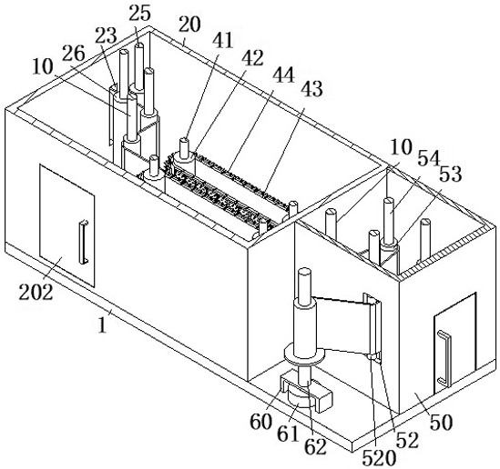
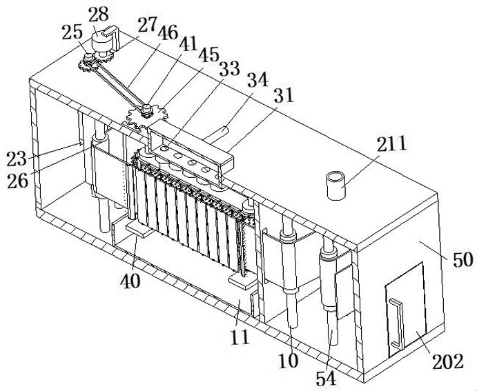
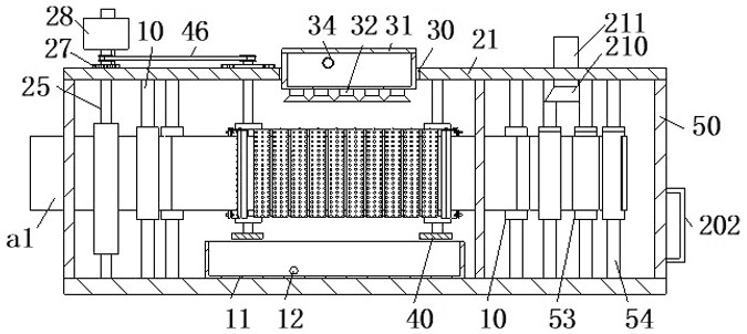
[0026] Such as Figure 1 to Figure 6 As shown, an electrolytic copper foil manufacturing and processing equipment includes a bottom plate 1, a transmission mechanism 2, a water spray mechanism 3, a scrubbing mechanism 4, a drying mechanism 5 and a winding mechanism 6. The upper end surface of the bottom plate 1 is viewed from the left A transmission mechanism 2, a scrubbing mechanism 4 and a drying mechanism 5 are arranged in sequence to the right, a water spray mechanism 3 is arranged above the scrubbing mechanism 4, and a winding mechanism 6 is arranged in front of the drying mechanism 5.

[0027]The conveying mechanism 2 includes a rectangular frame 20, an L-shaped top plate 21, a cleaning chamber 22, a feed trough 23, a discharge trough 24, a ro...


PUM


Abstract

The invention relates to the technical field of electrolytic copper foil manufacturing and processing, in particular to an electrolytic copper foil manufacturing and processing equipment, including a bottom plate, a transmission mechanism, a water spray mechanism, a scrubbing mechanism and a drying mechanism. A winding mechanism is arranged in front of the drying mechanism. The water spraying mechanism adopted in the present invention sprays water from above the copper foil for cleaning, and then the conveyor belt on the scrubbing mechanism drives the cleaning brush to scrub the copper foil, and the cleaning brush on the conveyor belt continuously cleans the copper foil. Scrubbing increases the contact area with the copper foil, which can effectively clean the impurities adhering to the copper foil, avoiding the phenomenon of poor cleaning effect of the copper foil, and the drying mechanism adopted at the same time can Wipe the sponge layer of the copper foil and dry it, so that the sponge layer can effectively absorb the water stains on the copper foil, and avoid the water stains remaining when the copper foil is wound.

Description

technical field [0001] The invention relates to the technical field of electrolytic copper foil manufacturing and processing, in particular to an electrolytic copper foil manufacturing and processing equipment. Background technique [0002] Electrolytic copper foil refers to the use of electrolytic copper or wire return materials of the same purity as raw materials, dissolved in a solution containing copper sulfate, and a cathode roll that uses insoluble materials as an anode and is dipped in copper sulfate electrolyte at a constant speed at the bottom. Electrolysis is carried out in the electrolytic cell of the cathode, and the copper in the solution is deposited on the surface of the cathode roller to form copper foil. The thickness of the copper foil is controlled by the cathode current density and the speed of the cathode roller. , and then continuously stripped from the cathode roll, the surface of the stripped copper foil may have residual impurities, so it needs to be...

Claims


Application Information

Patent Timeline
Patent Type & Authority Patents(China)
IPC IPC(8): B08B1/02B08B3/02B08B13/00F26B5/14F26B23/04
CPCB08B1/002B08B1/02B08B3/022B08B13/00F26B5/14F26B23/04
Inventor 陈向前
Owner SHENZHEN GOLF & FEIHUANG TECH
Why Eureka
Try Eureka