
Periscopic detection system capable of facing milling cutters and working method

A milling tool and detection system technology, which is applied in the field of periscope-oriented detection system for milling tools, can solve problems such as improper structural layout, inability to adjust independently, limitations of observation distance and observation angle, etc., and achieve a reasonable overall structure layout , Realize all-round shooting and improve work efficiency

Inactive Publication Date: 2021-08-20
SHANDONG UNIV
View PDF5 Cites 0 Cited by
  • Summary
  • Abstract
  • Description
  • Claims
  • Application Information

AI Technical Summary

Problems solved by technology

[0003] The applicant filed an application CN201910808367.9 in 2019, titled Periscope Detection Mechanism, Prediction System and Method for Cyclone Milling Tools. The device can enter the tool to take pictures of the tool state, which solves the problem of limited camera installation space in the prior art. The problem of the poor accuracy of the acquired image, but the inventor found that it also has the following problems:
The operation characteristics of conventional rotary milling machine tools are double rotation, that is, the cutter head rotates quickly, and the blank rotates slowly and accurately. arm for tool surface imaging
Under such conditions, when shooting different tools on a cutter head, the distance and angle between the lens and each tool are different, and the distance and angle between the objective lens and the tool surface cannot be adjusted flexibly. Subsequent testing sets up barriers
Not only that, because the observation point is fixed, the observation distance and observation angle are mutually restricted and cannot be adjusted independently
[0005] 2) Moreover, the adjustment of the entire movement requires the coordination of the machine tool and the working arm, which makes the programming more complicated
[0006] 3) The entire structure is improperly arranged, which is likely to affect the incoming light of the camera

Method used


Image

  • Periscopic detection system capable of facing milling cutters and working method
  • Periscopic detection system capable of facing milling cutters and working method
  • Periscopic detection system capable of facing milling cutters and working method

Examples


Embodiment Construction

[0039] It should be noted that the following detailed description is exemplary and intended to provide further explanation of the present invention. Unless defined otherwise, all technical and scientific terms used herein have the same meaning as commonly understood by one of ordinary skill in the art to which this invention belongs.

[0040] It should be noted that the terminology used here is only for describing specific embodiments, and is not intended to limit exemplary embodiments according to the present invention. As used herein, unless the invention clearly states otherwise, the singular form is also intended to include the plural form. In addition, it should also be understood that when the terms "comprising" and / or "comprising" are used in this specification, their Indicate the presence of features, steps, operations, means, components and / or combinations thereof;

[0041] Explanation of terms: The terms "installation", "connection", "connection", "fixation" and oth...

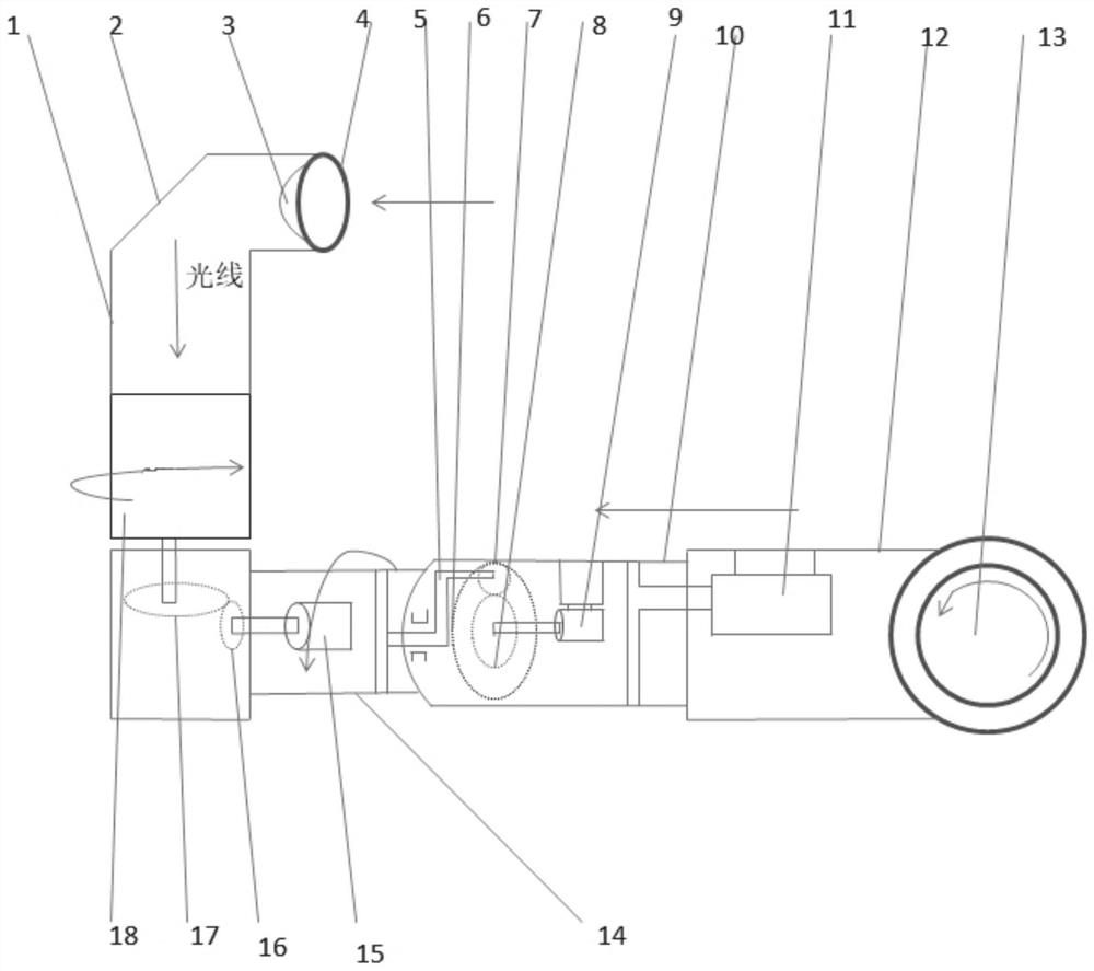

PUM


Abstract

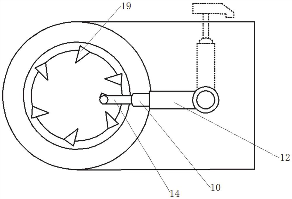
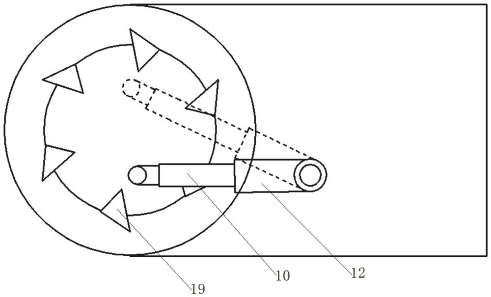
The invention discloses a periscopic detection system capable of facing milling cutters and a working method, solves the problem that in the prior art, the distance between lens cones and cutters cannot be adjusted, and has the beneficial effect that all-directional shooting of each cutter can be realized. According to the specific scheme, the periscopic detection system capable of facing the milling cutters comprises working arms rotationally installed on a whirlwind milling machine, the side portion of the other end, away from the whirlwind milling machine, of each working arm is provided with a hollow periscopic lens cone, a camera shooting component is arranged in each lens cone, and an objective lens is arranged at one end of each lens cone; and the at least three sections of working arms are arranged, and the working arms are arranged in a telescope manner to match rotation of the working arms, so that the working arms drive the lens cones to move to the side portions of the cutters in a cutter head, the sections, close to the lens cones, of the working arms can drive the lens cones to rotate, the lens cones can be converted into an observation state and enter the cutter head, and the lens cones can rotate relative to the working arms.

Description

technical field [0001] The invention relates to the field of milling tools, in particular to a periscope-type detection system and working method that can face milling tools. Background technique [0002] The statements in this section merely provide background information related to the present invention and do not necessarily constitute prior art. [0003] The applicant filed an application CN201910808367.9 in 2019, titled Periscope Detection Mechanism, Prediction System and Method for Cyclone Milling Tools. The device can enter the tool to take pictures of the tool state, which solves the problem of limited camera installation space in the prior art. The problem of the poor accuracy of the acquired image, but the inventor found that it also has the following problems: [0004] 1) During the inspection process, the entire rotary milling machine does not stop completely, but runs slowly to ensure that every tool can be photographed. The operation characteristics of conven...

Claims


Application Information

Patent Timeline
Patent Type & Authority Applications(China)
IPC IPC(8): B23Q17/24
CPCB23Q17/2457
Inventor 刘日良王孝文曾云飞
Owner SHANDONG UNIV
Learn More