Composite material winding pipe, inflation core mold and composite material winding pipe machining method
A composite material and winding pipe technology, applied in the field of building materials, can solve the problems of high structural strength and interface slippage, and achieve the effect of good corrosion resistance, good integrity, and improved interface performance.
- Summary
- Abstract
- Description
- Claims
- Application Information
AI Technical Summary
Problems solved by technology
Method used
Image
Examples
Embodiment 1
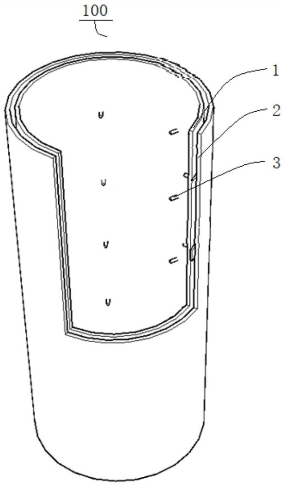
[0107] A composite winding tube 100, such as figure 1 As shown, it includes: a first structural layer 1, a second structural layer 2 and a shear key 3.
[0108] Among them, such as figure 1 As shown, the second structural layer 2 is connected outside the first structural layer 1 .
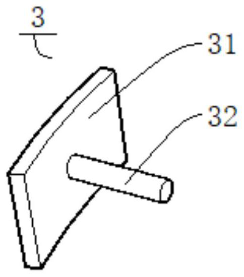
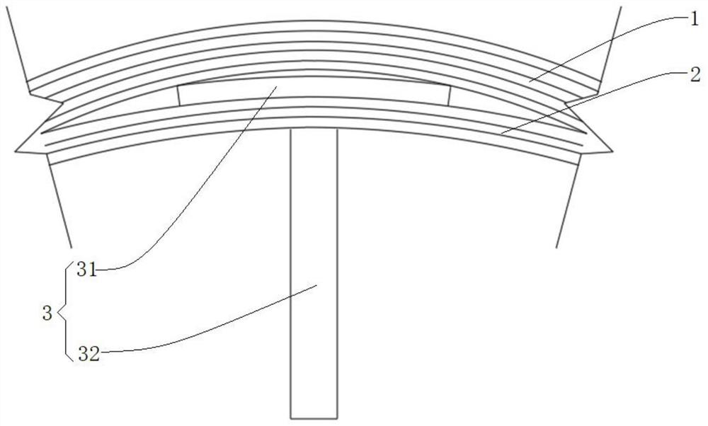
[0109] combine figure 1 and figure 2 As shown, the shear key 3 includes a matching portion 31 and a fixing portion 32, the matching portion 31 is connected between the first structural layer 1 and the second structural layer 2, one end of the fixing portion 32 is connected to the matching portion 31, and the other end of the fixing portion 32 One end protrudes from the first structural layer 1 in a direction away from the second structural layer 2 .
Embodiment 2
[0111] A kind of composite material winding pipe 100, different from Embodiment 1, such as figure 1 As shown, the composite winding pipe 100 is a cylindrical pipe, including: a first structural layer 1 , a second structural layer 2 and a shear key 3 .
[0112] Among them, such as figure 1 As shown, the second structural layer 2 is connected outside the first structural layer 1 .
[0113] combine figure 1 and figure 2 As shown, the shear key 3 includes a plurality of shear keys 3 arranged at intervals on the first structural layer 1, the shear key 3 includes a matching portion 31 and a fixing portion 32, the matching portion 31 is a sheet with curvature, and the matching portion 31 is a sheet with a curvature. The part 31 is connected between the first structural layer 1 and the second structural layer 2; the fixed part 32 is rod-shaped, and one end of the fixed part 32 is connected to the mating part 31, and the other end of the fixed part 32 faces away from the second str...
Embodiment 3
[0115] A kind of inflatable mandrel 200, such as Figure 4 As shown, it includes: an air bag 210 and a fixing column 220 .
[0116] Among them, such as Figure 4 As shown, the fixed columns 220 are arranged on opposite sides of the airbag 210, and the airbag 210 is provided with an inflatable and deflated air valve 2101. The airbag 210 is cylindrical as a whole and an inflatable cavity is formed inside, and the surface of the airbag 210 is concave toward the direction of the inflatable cavity. A plurality of fixing grooves 2102 are formed in the fixing grooves 2102, and the fixing part 32 in the composite material wrapping tube 100 of the second embodiment can be positioned in the fixing grooves 2102.
PUM
 Abstract
Description
Claims
Application Information
 - R&D
- Intellectual Property
- Life Sciences
- Materials
- Tech Scout
- Unparalleled Data Quality
- Higher Quality Content
- 60% Fewer Hallucinations
Browse by: Latest US Patents, China's latest patents, Technical Efficacy Thesaurus, Application Domain, Technology Topic, Popular Technical Reports.
© 2025 PatSnap. All rights reserved.Legal|Privacy policy|Modern Slavery Act Transparency Statement|Sitemap|About US| Contact US: help@patsnap.com


