
Fuel oil system of automobile and leakage detection method of fuel oil system

A fuel system and automobile technology, which is applied in the charging system, adding non-fuel substances to fuel, and fuel injection control, etc., can solve problems such as false alarms and detection errors.

Active Publication Date: 2021-08-20
YAPP AUTOMOTIVE PARTS
View PDF5 Cites 2 Cited by
  • Summary
  • Abstract
  • Description
  • Claims
  • Application Information

AI Technical Summary

Problems solved by technology

[0006] This application provides a fuel system of an automobile and a leak detection method of the fuel system, which fundamentally solves the problems of detection errors and false alarms caused by reference holes by measuring pressure and judging pressure drop

Method used


Image

  • Fuel oil system of automobile and leakage detection method of fuel oil system
  • Fuel oil system of automobile and leakage detection method of fuel oil system
  • Fuel oil system of automobile and leakage detection method of fuel oil system

Examples


Embodiment 1

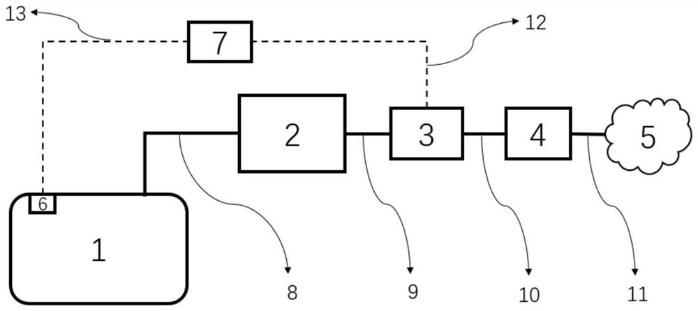
[0055] A car includes an engine and a fuel system. like figure 2 As shown, in this application, the fuel system includes a fuel tank 1, a fuel vapor recovery tank 2, a leak detection device, and an air filter 4. The fuel tank 1 is connected to the fuel vapor recovery tank 2 through a first pipeline 8, and the fuel vapor recovery Tank 2 is provided with an air outlet. At the same time, the vapor collected in the fuel vapor recovery tank 2 is transported to the engine through pipelines for recycling. There is a pressure sensor on the fuel system.

[0056] As an example, such as figure 2 As shown, the pressure sensor 6 is installed on the fuel tank 1 .

[0057]The leak detection device includes a microcontroller 7, a detector 3 and a pressure regulator. The microcontroller 7 is connected to the pressure sensor 6 through the first circuit 13 , the actuator of the pressure regulator is connected to the microcontroller 7 through the second circuit 12 , and the gas outlet of t...

Embodiment 2

[0078] The present application also provides a leakage detection method matched with the above-mentioned fuel system. like Figure 11 As shown, the leakage detection method includes the following steps:

[0079] S1110: In response to receiving the leakage detection signal, control the actuator of the pressure regulator to run at the first rotational speed, the driving mechanism of the first spool drives the first spool to close, the second spool remains closed, and the fuel system Cheer up.

[0080] S1120: In response to the pressure of the fuel system reaching a predetermined pressure, the actuator controlling the pressure regulator stops running, and the pressure of the fuel system is maintained by means of the pressure maintaining function of the pressure regulator.

[0081] S1130: Collect the pressure signal of the fuel system.

[0082] S1140: Determine whether the duration of pressure collection reaches a preset duration. If yes, execute S1150 and S1190.

[0083] S1150...


PUM


Abstract

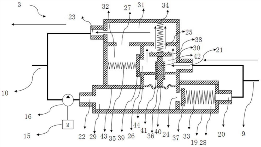
The invention discloses a fuel oil system of an automobile and a leakage detection method of the fuel oil system. The fuel oil system comprises a fuel oil steam recovery tank and a leakage detection device; the leakage detection device comprises a microcontroller, a detector and a pressure regulator; the microcontroller is in signal connection with a pressure sensor; an execution mechanism of the pressure regulator is in signal connection with the microcontroller, and a gas outlet of the pressure regulator is connected with the fuel oil steam recovery tank; the detector is installed between the fuel oil steam recovery tank and the atmosphere and comprises a first cavity, a second cavity and a third cavity, an air inlet of the first cavity is connected with an air outlet of the fuel oil steam recovery tank, and an air outlet of the second cavity is communicated with the atmosphere; a first valve element is arranged between the first cavity and the second cavity and closed through a driving mechanism of the first valve element; a second valve core is arranged between the third cavity and the first cavity; and the third cavity is communicated with the second cavity. According to the fuel oil system provided by the invention, the problems of detection errors and false alarms caused by reference holes are solved.

Description

technical field [0001] The present application relates to the technical field of automobiles, and more specifically, relates to a fuel system of an automobile and a method for detecting leakage of the fuel system. Background technique [0002] The requirements for vehicle emissions in laws and regulations are getting higher and higher. At present, more and more vehicles are designed with leakage detection modules. This leakage detection module can detect the leakage of tiny holes in the entire fuel system to prevent fuel leakage and ensure The tightness of the fuel system protects the environment and ensures the safety of vehicles. [0003] At present, the main leakage detection method is to use the reference hole set on the leakage detection module to determine the current change standard value of the motor or the pressure change standard value of the fuel system, and use the current change value or pressure change standard value as a reference value to evaluate Leakage in...

Claims


Application Information

Patent Timeline
Patent Type & Authority Applications(China)
IPC IPC(8): F02D41/22F02M25/08
CPCF02D41/22F02M25/08F02D2041/225
Inventor 姜林高德俊吕昊苏卫东李进刘亚洲周传军张艳波严济彦吴旭东任业荀祥
Owner YAPP AUTOMOTIVE PARTS
Learn More