
Vehicle lamp optical element, headlamp module, vehicle lamp and vehicle

A technology for optical components and headlights, which is applied to headlights, road vehicles, vehicle parts, etc., can solve the problems of heating and deformation of optical components of lights, reducing the utilization rate of light of optical components of lights, and reducing the life of lights, etc. To achieve the effect of not easy to wear

Pending Publication Date: 2021-08-20
HASCO VISION TECHNOLOGY CO LTD
View PDF0 Cites 0 Cited by
  • Summary
  • Abstract
  • Description
  • Claims
  • Application Information

AI Technical Summary

Problems solved by technology

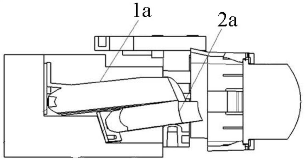
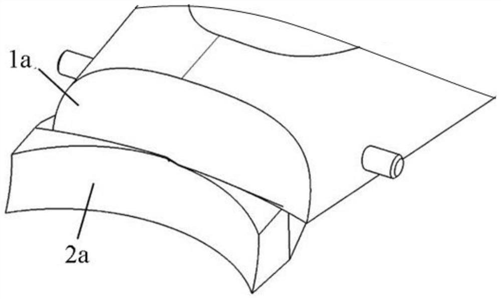
[0003] However, since the low-beam optical element 1a and the high-beam optical element 2a are in contact with each other or are relatively close to each other, the two are made of the same material and are generally made of hard PC or PMMA. There is a dark area at the junction of the beam shape and the high beam shape. Moreover, when the lights vibrate, they will rub against each other to a certain extent, which will further aggravate the degree of wear of the two, and even wear to the point of powdering, which affects the light. The stability of the outgoing light shape reduces the service life of the car lamp. At the same time, due to the wear between the two, the distance between the front end of the low beam optical element 1a and the high beam optical element 2a increases, which will make the low beam light shape and the high beam The dark area at the junction of light and shape is more obvious
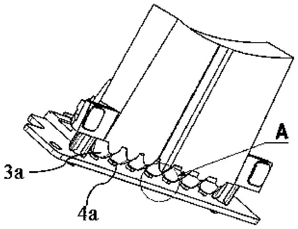
[0004] In addition, refer to image 3 and Figure 4 , the car light optical element in the prior art, its focusing cup 3a and the light source 4a are arranged close to each other, and a large amount of heat is generated after the light source 4a is turned on, which will cause the focusing cup 3a to be deformed or melted by heat, and affect the light shape emitted by the car light. It will have an impact, seriously affect the performance of the lights, and even cause damage to the lights, which will bring great hidden dangers to traffic safety.
[0005] In order to solve the problem of heating and deformation of the optical components of the car lights, those skilled in the art have adopted the following solutions: (1) Set the distance between the focusing cup 3a and the light source 4a to a relatively large value, generally at least 0.5mm, and some even reach 1~2mm, so that the light source 4a is as far away from the light source 4a as possible, but the distance between the light source 4a and the light source 4a is set too large, which will cause the optical efficiency of the lamp to be lost; (2) the light source 4a is placed close to the light source 4a One end is partially cut to keep a certain distance between the focusing cup 3a and the light source 4a, but the cutting of the focusing cup 3a will also reduce the light utilization rate of the optical components of the car light, which will damage the optical efficiency of the car light
[0006] To sum up, the light-emitting end of the optical components of the car lights in the prior art cannot reduce the degree of wear and tear of the car lights while ensuring the uniform connection between the low-beam light shape and the high-beam light shape, and the light-incoming end cannot take into account cost, optical efficiency and High temperature performance

Method used


Image

  • Vehicle lamp optical element, headlamp module, vehicle lamp and vehicle
  • Vehicle lamp optical element, headlamp module, vehicle lamp and vehicle
  • Vehicle lamp optical element, headlamp module, vehicle lamp and vehicle

Examples


Embodiment Construction

[0045] The specific embodiments of the present invention will be described in detail below in conjunction with the accompanying drawings. It should be understood that the specific embodiments described here are only used to illustrate and explain the present invention, and the protection scope of the present invention is not limited to the following specific embodiments. .

[0046] It should be understood that if Figure 5, based on the car light optical element, when it is normally installed in the car light, along the light emitting direction, "front" refers to the end where the second light-transmitting part 13 is located, "rear" refers to the end where the light-concentrating part 11 is located, and "upper "Refers to the upper direction along the light emitting direction, and "down" refers to the lower direction along the light emitting direction. In the actual installation situation, the orientation term should be explained based on the actual installation status and the ...


PUM


Abstract

The invention relates to a vehicle lighting device, and discloses a vehicle lamp optical element which comprises a light condensation part (11), a first light transmission part (12) and a second light transmission part (13) which are sequentially arranged, the light condensation part (11), the first light transmission part (12) and the second light transmission part (13) are integrally formed parts, the light condensation part (11) and the second light transmission part (13) are silica gel formed parts, and the first light transmission part (12) is a plastic formed part. In addition, the invention further discloses a headlamp module, a vehicle lamp and a vehicle. The vehicle lamp optical element has the advantages of low cost, high temperature resistance and wear resistance.

Description

technical field [0001] The present invention relates to a vehicle lighting device, in particular to a vehicle light optical element. In addition, the present invention also relates to a headlight module, a vehicle light and a vehicle comprising the vehicle light optical element. Background technique [0002] In the prior art, in order to form the low-beam light shape and the high-beam light shape of the vehicle, the low-beam optical element 1a and the high-beam optical element 2a are provided in the vehicle lamp at the same time. And, refer to figure 1 and figure 2 , in order to achieve a good connection between the low-beam light shape and the high-beam light shape, and avoid forming a dark area at the junction of the low-beam light shape and the high-beam light shape, the front ends of the above two optical elements are in contact with each other, or only a small distance apart (Generally less than 1mm). [0003] However, since the low-beam optical element 1a and the ...

Claims


Application Information

Patent Timeline
IPC IPC(8): F21S41/30F21S41/25F21S41/24F21W102/135F21W107/10
CPCF21S41/24F21S41/25F21S41/30F21W2102/135F21W2107/10
Inventor 仇智平祝贺严海月桑文慧
Owner HASCO VISION TECHNOLOGY CO LTD
Learn More