

A UHF RFID anti-metal tag antenna based on microstrip structure
An anti-metal tag, ultra-high frequency technology, applied in the direction of antenna, antenna parts, radiating element structure, etc., can solve the problems of complex processing, narrow frequency band, high cost, reduce the actual size, widen the bandwidth, good broadband Effects with properties
Active Publication Date: 2022-05-31
NINGBO UNIV
View PDF14 Cites 0 Cited by
- Summary
- Abstract
- Description
- Claims
- Application Information
AI Technical Summary
Problems solved by technology
However, the ultra-high frequency RFID anti-metal tag antenna based on the microstrip structure usually needs to use metal vias, short-circuit patches, or dielectric substrates with high dielectric constants, etc. The processing is complicated, the cost is high, and the frequency band is narrow.
Method used
View moreImage
Smart ImageViewing Examples

Examples
Embodiment
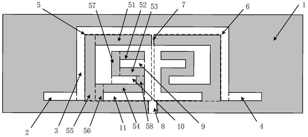
[0015] In the present embodiment, the dielectric substrate adopts the epoxy glass cloth laminate with a thickness of 1.5mm to realize, the first rectangular groove 2,
[0016] In this embodiment, the length of the dielectric substrate in the left-right direction is 73 mm, and the length in the front-rear direction is 24 mm; the first
Login to View More PUM
| Property | Measurement | Unit |
|---|---|---|
| thickness | aaaaa | aaaaa |
| length | aaaaa | aaaaa |
| length | aaaaa | aaaaa |
Abstract
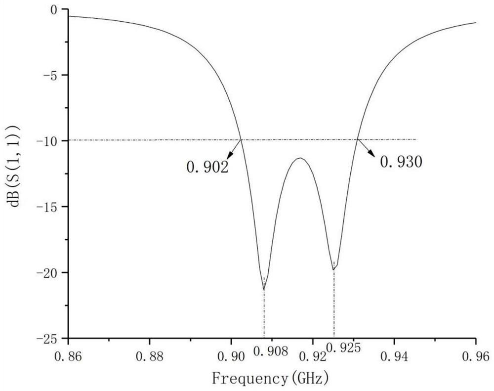
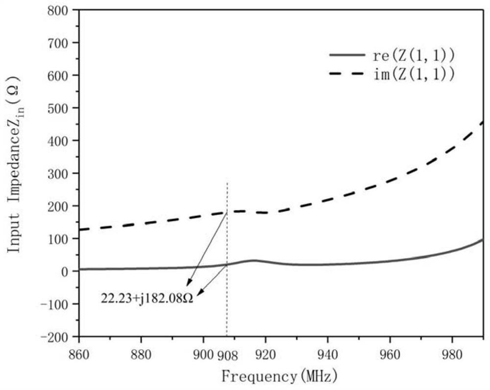
The invention discloses an ultra-high frequency RFID anti-metal tag antenna based on a microstrip structure, which includes a dielectric substrate and a radiation module arranged on the dielectric substrate. The dielectric substrate is a rectangular plate, and the radiation module is realized by a microstrip structure. The radiation module includes The radio frequency chip, the metal layer, the first rectangular slot, the second rectangular slot, the third rectangular slot, the first radiation unit and the second radiation unit, the first radiation unit and the second radiation unit are respectively composed of eight rectangular metal blocks, the second The first radiating unit and the second radiating unit not only form a symmetrical dipole antenna structure, but also form a U-shaped slot connected with the first rectangular slot and the third rectangular slot with the second rectangular slot. The gap formed between them and the internal gap constitute an impedance adjustment structure; the advantage is that it has a long reading distance, high gain, miniaturization, simple processing technology, low cost, and wide frequency band.
Description
A UHF RFID Anti-Metal Tag Antenna Based on Microstrip Structure technical field The present invention relates to a kind of ultra-high frequency RFID anti-metal tag antenna, especially relate to a kind of ultra-high frequency based on microstrip structure [0001] High frequency RFID anti-metal tag antenna. Background technique With the promotion of Internet of Things technology in various fields, the application scenarios of radio frequency identification technology (RFID) tags are gradually becoming more and more popular. Due to diversity, some applications require RFID tag antennas to be mounted on items of different materials, such as glass, wood, or even on metal. The RFID tag antenna is usually directly attached to the object that needs to be identified, while the metal object is very sensitive to the RFID tag antenna. is very challenging. When an ordinary RFID tag antenna is placed on the surface of a metal object, it will encounter gold due to electromagnetic ...
Claims
Login to View More Application Information
Patent Timeline
 Patent Type & AuthorityPatents(China)
IPC IPC(8): H01Q1/22H01Q1/38
CPCH01Q1/2225H01Q1/38
Inventor王健陈德怀时稳霍建建
OwnerNINGBO UNIV