
Component identification

A technology of components and identification modules, applied in the fields of electrical components, separation methods, pulse technology, etc., can solve the problems of missed alarms, the introduction of complexity into the identification system, and false alarms.

Pending Publication Date: 2021-08-20
CATERPILLAR INC
View PDF1 Cites 0 Cited by
  • Summary
  • Abstract
  • Description
  • Claims
  • Application Information

AI Technical Summary

Problems solved by technology

Such signals can require significant time and processing resources to interpret and can introduce complexity into the recognition system, which can lead to system failures, false positives, false negatives, etc.

Method used


Image

  • Component identification
  • Component identification
  • Component identification

Examples


Embodiment Construction

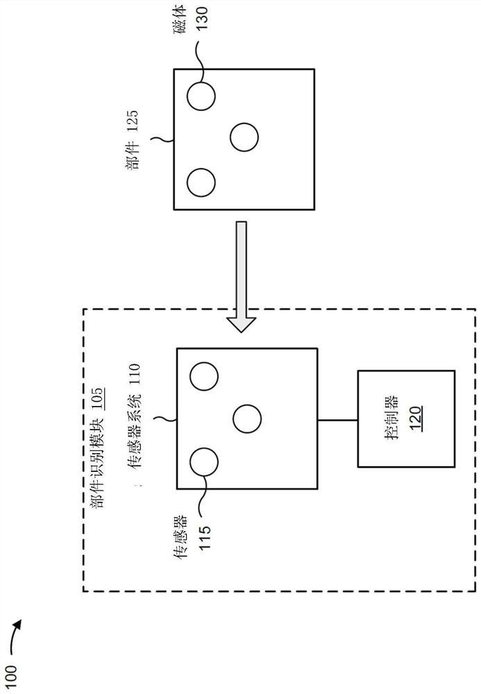
[0011] The present disclosure relates to a component identification system. The component identification system has general applicability to any machine that utilizes one or more components that may be replaced during the machine's lifetime. The term "machine" may refer to any machine that performs operations associated with an industry such as mining, construction, agriculture, transportation, or any other industry. As some examples, the machine may be a vehicle, backhoe loader, cold planer, wheel loader, compactor, feller buncher, forestry machine, forwarder, harvester, excavator, industrial loader, steering Boom loaders, material handlers, motor graders, pipelayers, road reclaimers, skid steer loaders, skidders, telehandlers, tractors, bulldozers, tractor scrapers or other aboveground equipment, underground equipment or marine equipment.

[0012] figure 1 is a diagram of an exemplary part identification system 100 . like figure 1 As shown in , the part identification s...


PUM


Abstract

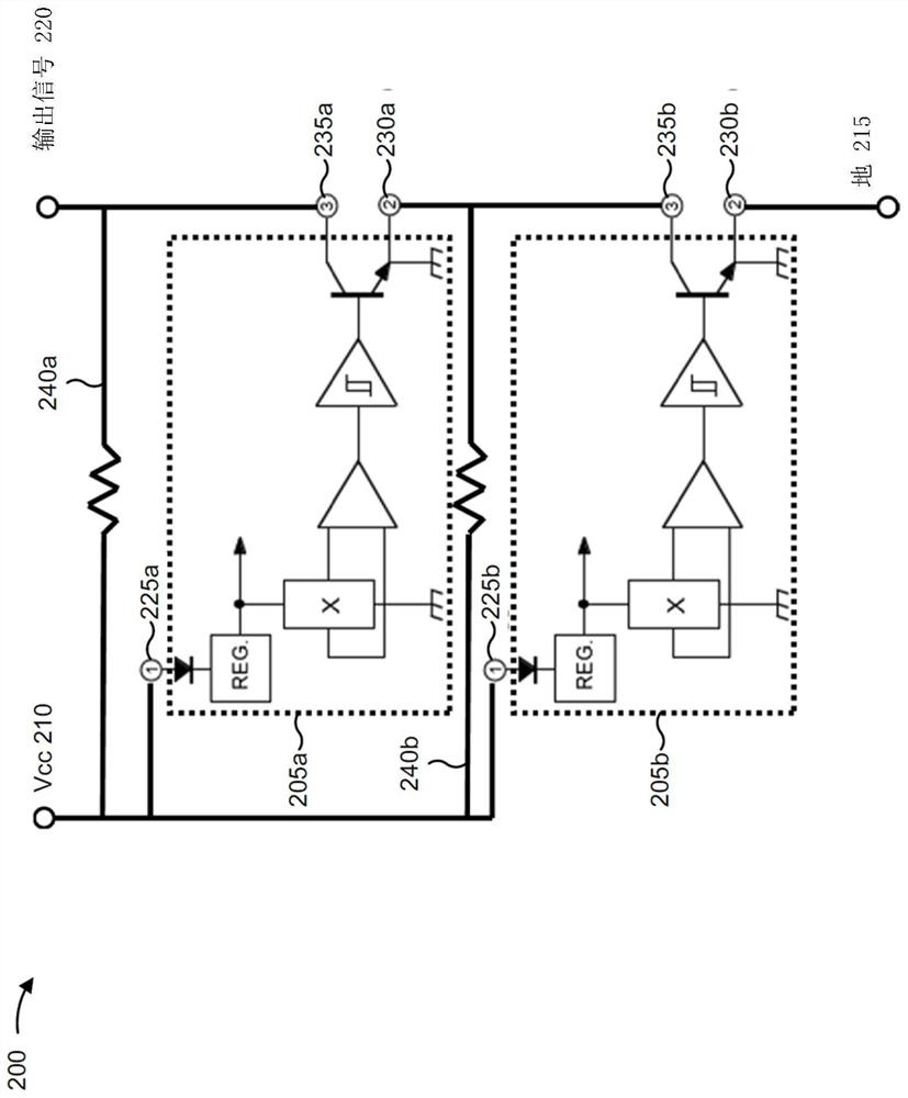
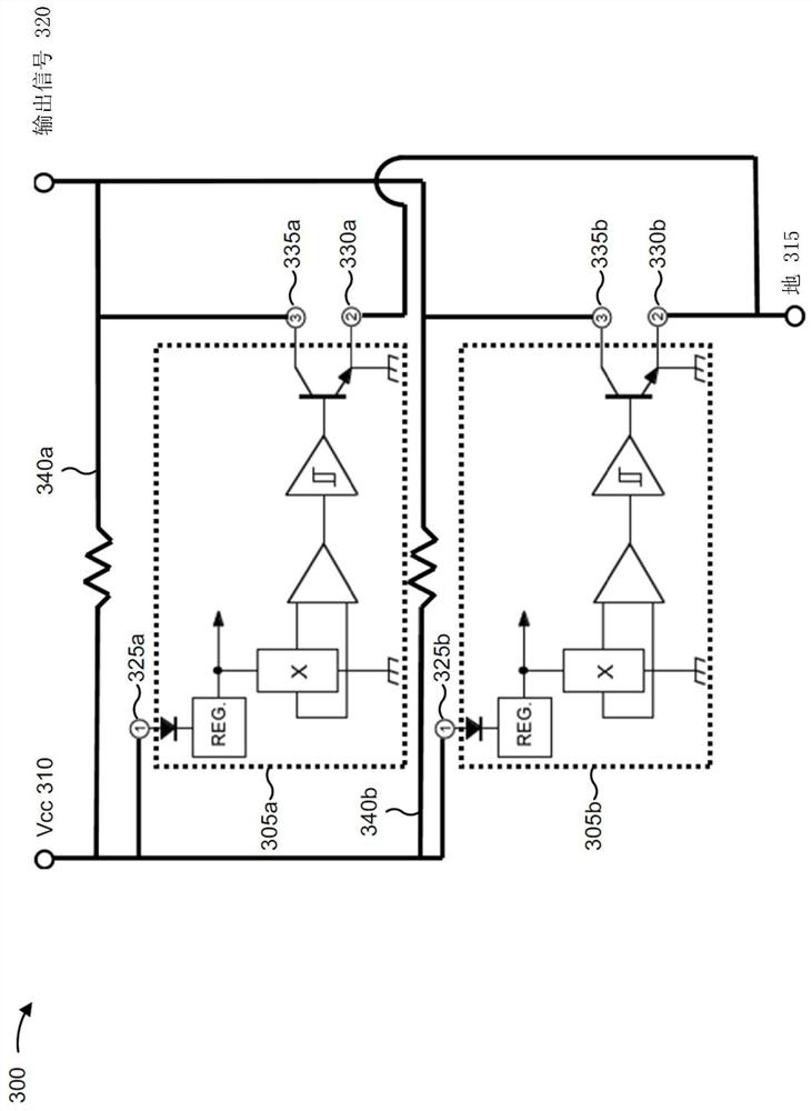
A component identification system is disclosed. The component identification system may include a sensor system that includes a first Hall-effect switch configured to provide a first output signal corresponding to a state of the first Hall-effect switch, and a second Hall-effect switch configured to provide a second output signal corresponding to a state of the second Hall-effect switch. The sensor system may be configured to provide a single output signal that is based on the first output signal and the second output signal and indicates a combined state of the first Hall-effect switch and the second Hall-effect switch. The component identification system may include a component that is to be identified. The component may include a first magnet configured to affect the state of the first Hall-effect switch and a second magnet configured to affect the state of the second Hall-effect switch.

Description

technical field [0001] The present disclosure relates generally to component identification and, for example, to component identification using Hall effect switches. Background technique [0002] A machine consists of several parts that work together to perform various operations in the machine. Some of these components may need to be replaced at some stage of machine operation due to wear, reaching end of life, etc. Such parts may be targeted by counterfeiters, who may manufacture poorly designed or otherwise inferior replica parts. Consequently, these duplicate parts may not meet the standards of the original parts (for example, as set by the original equipment manufacturer (OEM)) and may result in poor performance, damage to the machine and related accessories, low user satisfaction with the machine, etc. . [0003] An attempt at a magnetic anti-counterfeit label and identification system is disclosed in US Patent Application Publication No. 20170200028 (“the '028 publ...

Claims


Application Information

Patent Timeline
IPC IPC(8): H03K17/90
CPCH03K17/90H03K17/95G01R33/0058G01R33/072B01D2201/52G01R33/0023G01R33/0088G01D5/145
Inventor M·T·麦金利田野
Owner CATERPILLAR INC
Learn More