[0032] The present invention will be described in detail below with reference to the accompanying drawings and in conjunction with the embodiments. It should be noted that the embodiments of the present invention and the features of the embodiments may be combined with each other under the condition of no conflict. For the convenience of description, the words "up", "down", "left" and "right" appear in the following text, which only means that the directions of up, down, left and right are consistent with the drawings themselves, and do not limit the structure.
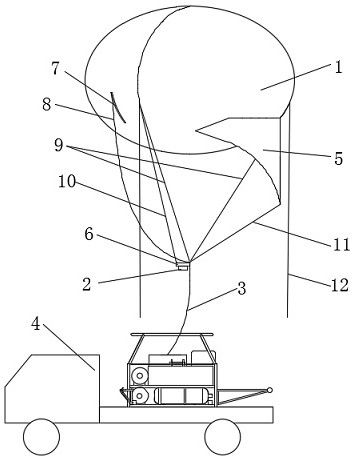
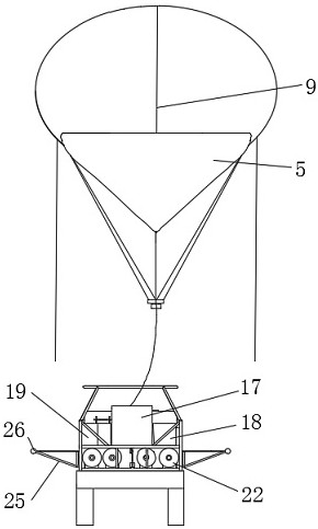
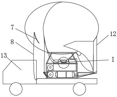
[0033] like figure 1 , 2 As shown, a vehicle-mounted tethered floating information support platform system provided in this embodiment includes a mooring balloon 1, a mission load 2, a mooring cable 3, a cable assembly, a load pylon 6 and a mooring with a transport chassis 13. car 4.
[0034] The mooring balloon 1 has an oblate spherical shape, and a flexible windbag tail 5 is installed at the tail, and the windbag tail 5 is used to provide dynamic lift and maintain heading stability.
[0035] The vehicle-mounted tethered floating information support platform system is integrated on the transport chassis 13 . The transport chassis 13 of the anchor parking vehicle 4 is provided with a load-bearing box 14, and the load-bearing box 14 is loaded to meet the size requirements of conventional light truck transport vehicles or other models, and the general length and width are not more than 2m, and the height is not higher than 1.7m.
[0036] like Figure 5 , 6 As shown, the main body of the load-bearing box 14 is a frame welded by section steel, and a main winch 15, a cable winch 16, a gas cylinder 22, a generator 17 and a power supply battery 18 are installed inside. The load-bearing box 14 is also provided with an electrical control box 19 and an equipment storage box 20. The electrical control box 19 and the equipment storage box 20 are respectively installed on both sides of the main winch 15, and a load bracket is arranged above the electrical control box 19. The rack 21 is used to place the task load 2 and the load rack 6 when anchoring (such as Figure 4 shown).
[0037] like figure 2 , 5 , 6, a plurality of gas cylinders 22 are installed on the bottom and one side of the main winch 15. Each of said cylinders 22 can provide 20m 3 of helium. The gas cylinder 22 is connected to the inflation tube through the bus bar, and the inflation tube is connected to the captive balloon 1 . The number of gas cylinders 22 is generally 4~6, which can be lifted to meet the sphere volume of 110m 3 The following tethered balloons are filled with helium for the first time and the amount of refilling during the long-term stay in the air.
[0038] The mooring ring 24 supported by a plurality of vertical rods 23 is provided on the top of the mooring car 4 , which is used to support the mooring balloon 1 during mooring, and can also restrict the movement direction of the mooring cable 3 . The bottom of the mooring balloon 1 is evenly distributed with a plurality of pull rings, which are connected to the mooring ring 24 through a binding rope to fix the mooring balloon 1 on the mooring ring 24 .
[0039]Three foldable anchoring arms 25 and three cable winches 16 are provided on the side of the load-bearing box 14 , and the anchoring arms 25 are concentric with the anchoring ring 24 . The concentricity means: the center of a circle drawn by connecting the hinge axes of the three anchoring arms 25 is concentric with the center of the anchoring ring 24 . The anchoring bracket 25 is a right-angled triangle, and the short side of the right angle is hinged with the load-bearing box 14 , and the anchoring bracket 25 can be folded or unfolded toward the direction of the load-bearing box 14 along the hinge axis. A guide wheel 26 is provided on the top corner of the right-angled triangle. The guide wheel 26 is used to limit the movement direction of the mooring cable 12 .
[0040] The three cable winches 16 are respectively installed on the sides of the hinge shafts of the three anchoring arms 25 , and the three mooring cables 12 are connected to the corresponding cable winches 16 through the guide pulleys 26 of the anchoring arms 25 . The cable winch 16 can tighten the mooring cable 12, so that the mooring balloon 1 is anchored on the mooring ring 24, and can also release the mooring cable 12, so that the mooring balloon 1 is released from the mooring state and starts to lift off. 16 can be linked or controlled individually.
[0041] The generator 17 and the power supply battery 18 are electrically connected to the mooring cable 3, the main winch 15, and the cable winch 16 to provide system power, and a mains interface is provided. 15 side of the winch (eg figure 2 , 5 shown). Specifically: the generator 17 and the power supply battery 18 are arranged on the back side of the main winch 15 , the gas cylinder 22 is arranged on the front side of the main winch 15 ; the equipment storage box 20 is arranged on the right side of the main winch 15 , the electrical control box 19 is arranged on the left side of the main winch. The front, rear, left, and right above are based on a person sitting in the cab as a reference. The equipment storage box 20 and the electrical control box 19 are located at the upper end of the gas cylinder 22 provided at the bottom of the main winch 15 .
[0042] like figure 1 , 3 As shown, a tearing web 7 is installed on the captive balloon 1, and a safety rope 8 is fastened on the tearing web 7. The safety rope 8 is connected to the mooring cable 3 when the mooring balloon 1 is lifted and suspended, and the safety rope 8 is connected to the load-bearing box 14 when anchored. In emergency situations such as the escape of the tethered balloon 1, the tethered balloon 1 is torn through the safety rope 8, so that the tethered balloon 1 is deflated and quickly falls to the ground.
[0043] The mooring balloon 1 is installed with a cable assembly, and the cable assembly includes a shape cable 9 , a hanger cable 10 , a windbag cable 11 and a mooring cable 12 . The forming cable 9 converges from the top of the balloon along the rope loop on the ball to the mooring point of the mooring cable 3 under the ball, and the balloon is drawn into a full shape by the tension of the forming cable 9 . One end of the hanger cable 10 is connected to the mooring balloon 1 , and one end is connected to the hanging point of the load hanger 6 . One end of the windbag cable 11 is connected to the bottom of the windbag tail 5 , and one end is connected to the mooring point of the mooring cable 3 or the formed cable 9 , for restricting the movement of the windbag tail 5 . The number of the mooring cables 12 corresponds to the number of the mooring brackets 25 and the cable winches 16 . The three mooring cables 12 are evenly distributed on the side surface of the mooring balloon 1 , and the lower ends of the three mooring cables 12 are connected to the mooring cable winch 16 for mooring the mooring balloon 1 .
[0044] The load pylon 6 is internally provided with a power conversion module and a structural interface, and is electrically connected with the mooring cable 3 and the task load 2 . The upper side of the load hanger 6 is provided with three hanging points evenly distributed above the load hanger 6, two of which are connected to the mooring balloon 1 through two hanger cables 10, and the other hanging point is connected to the tethered balloon 1. At the mooring point of the mooring cable 3. The load hanger 6 is set in a waterproof box shape, and other functional components required for the load such as a power conversion module are installed inside. According to the load requirements, it can also be in other shapes.
[0045] The mission load 2 includes cameras, communication equipment, lighting loads, etc., and the type and combination of loads are also selected according to usage requirements. The task load 2 is installed on the lower side (bottom) of the load rack 6, and can also be installed in other positions according to the requirements of use.
[0046] The mooring cable 3 selects a power supply composite cable or a photoelectric composite cable, one end of which is connected to the main winch 15, and the other end is connected to the mooring balloon 1 through a formed cable 9, which is used for pulling and mooring the balloon 1, and providing equipment on the ball. For power transmission, it can also be used for communication between the mooring balloon 1 and the ground when the optoelectronic composite cable is selected.
[0047] When performing the task, the anchor car 4 is powered on through the mains or generator 17, the mooring balloon 1 is deployed near the load-bearing box 14, the main winch 15 is activated to release the mooring cable 3, and the mooring cable 3 passes through the mooring ring 24. Connect with the mooring balloon 1, connect the mooring balloon 1 and the inflation tube to inflate, transfer the mooring balloon 1 to the top of the mooring car 4 after the inflation is completed, unfold the mooring arm 25, and pass the end of the mooring cable 12 through the guide wheel 26 is connected to the cable winch 16, controls the cable winch 16 to recover the mooring cable 12, lowers the height of the mooring balloon 1 until the operator can reach the pylon cable 10, installs the load pylon 6 and the task load 2, in turn Release the mooring cable 12 and mooring cable 3, so that the mooring balloon 1 is gradually lifted to the working height and enters the information support state.
[0048] During the task waiting process or after a single task is completed, when the main winch 15 is controlled to recover the mooring cable 3 to near the ground, the end of the mooring cable 12 is connected to the cable winch 16 through the guide wheel 26, and the cable winch 16 is controlled to recover Tie down the mooring cable 12, lower the mooring balloon 1 until it is in contact with the mooring ring 24, and connect the bottom tab of the mooring balloon 1 to the mooring ring 24 to assist in fixing the mooring balloon 1. During the descending process of the mooring balloon 1, the entire mission load 2 and the load hanger 6 are placed on the load bracket 21.
[0049] When the mission is no longer performed, remove the mission load 2 and put it into the packing box, deflate the mooring balloon 1, disconnect it from the mooring cable 3, fold it and place it on the anchor car 4, fold the mooring arm 25, and the system is disconnected. Electricity can be transported or stored.
[0050] The above descriptions are only the embodiments of the present invention, and are not intended to limit the scope of the present invention. Any equivalent structure or equivalent process transformation made by using the contents of the description and drawings of the present invention, or directly or indirectly applied to other related technologies Fields are similarly included in the scope of patent protection of the present invention.