A distributed ducted fan high-lift system and its application method

A ducted fan and distributed technology, which is applied in the field of distributed ducted fan high-lift systems, can solve the problems of lack of distributed power increase technology, distributed power high-efficiency lift, and heavy ducted fan weight, etc., to achieve favorable Flight control, increase cruising speed, solve the effect of low lift increment

Active Publication Date: 2021-11-30
INST OF HIGH SPEED AERODYNAMICS OF CHINA AERODYNAMICS RES & DEV CENT
View PDF20 Cites 0 Cited by
  • Summary
  • Abstract
  • Description
  • Claims
  • Application Information

AI Technical Summary

Problems solved by technology

The invention patent with the application number 201810315808.7 published in the Chinese patent literature database proposes a short take-off and landing UAV using distributed ducted fan power. Rolling distance; the short take-off and landing UAV projects the thrust to the vertical direction through power deflection, and indirectly converts the thrust into lift, which not only requires the support of a high-power power system, but also causes waste of power in the cruising state
Another problem with increasing the lift by deflecting the ducted fan is that for high-speed aircraft, the ducted fan is heavy, difficult to deflect, and difficult to mechanically design
[0004] At present, there is no system and its application method that can effectively solve the problem of high-efficiency lift generated by distributed power, especially the lack of a distributed power increase technology suitable for high-speed aircraft

Method used


Image

  • A distributed ducted fan high-lift system and its application method
  • A distributed ducted fan high-lift system and its application method
  • A distributed ducted fan high-lift system and its application method

Examples


Embodiment 1

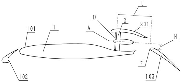
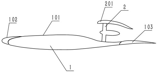
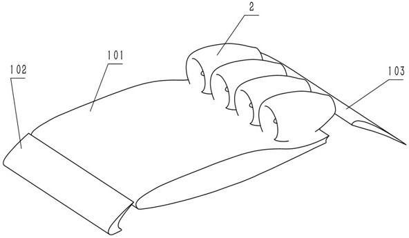
[0057] In this embodiment, four ducted fan propellers 2 arranged side by side are integrated on the back of the main wing 101 . The boost ratio of the ducted fan propeller 2 is 1.35. There is no interval between the ducted fan propellers 2, the ducted fan propeller cover 201 is higher than the highest point of the wing 1, and the distance between the ducted fan rotation axes A is the fan diameter D of the ducted fan propeller. Both the air inlet and the exhaust port of the ducted fan propeller 2 are circular.

[0058] When the wing 1 is in the open state, the sweep angle of the leading edge flap 102 is 0°, and the front and rear distance L between the leading edge point F of the trailing edge flap and the fan fan surface of the ducted fan propeller is the fan diameter of the ducted fan propeller 2 times of D; the longitudinal distance H between the leading edge point F of the trailing edge flap and the ducted fan rotation axis A is 0.1 times the fan diameter D of the ducted f...


PUM


Abstract

The invention discloses a distributed ducted fan high-lift system and an application method thereof. The system includes wings and multiple ducted fan propellers; the wings are multi-section wings, at least including the main wing and trailing edge flaps, with optional leading edge flaps; the ducted fan propellers are installed side by side at the tail of the main wing upper surface. In this method, in the boost mode, the trailing edge flaps are opened to form a high-speed jet airfoil to generate greater lift; in the cruise mode, the trailing edge flaps are retracted to form the lower compression surface of the nozzle to increase the jet flow speed, to increase the cruising speed; in the control mode, the trailing edge flaps are deflected to the corresponding position according to the torque demand, providing control torque for the aircraft. The system and method realize the integrated design of duct power and wing, solve the problems of low lift increment and high drag increment existing in the traditional lift-increasing method, and achieve improvement in two aspects of aerodynamics and propulsion.

Description

technical field [0001] The invention belongs to the technical field of aircraft, and in particular relates to a distributed ducted fan high-lift system and an application method thereof. Background technique [0002] With the increasing demand for flying in special environments such as plateaus, islands, ships, and water, increasing the lift of aircraft to achieve short take-off and landing, increase load, or increase climb rate has become an urgent need for current transport aircraft. Traditionally, the measures to increase the lift of various types of transport aircraft (including civil aircraft) mainly include the increase of the front and rear edge flaps, the increase of the power of the engine tail jet flow, and the increase of the propeller slipstream. Although these types of lift-increasing measures can bring higher low-speed lift increments and smaller high-speed cruising resistance increments, they bring large drag increments when taking off at low speeds, resulting...

Claims


Application Information

Patent Timeline
Patent Type & Authority Patents(China)
IPC IPC(8): B64C9/18B64C9/24
CPCB64C9/18B64C9/24
Inventor 达兴亚李永红郭龙凯李阳赵捷朱耀武袁培博雷子菡谢翔
Owner INST OF HIGH SPEED AERODYNAMICS OF CHINA AERODYNAMICS RES & DEV CENT
Why Eureka
Try Eureka