
Multi-winding composite traction elevator and adjusting method

An adjustment method and multi-winding technology, applied in the field of elevators, can solve the problems of small elevator load, small traction ratio, and adding elevators, and achieve the effects of high traction ratio, reduced failure rate, and reduced cost

Active Publication Date: 2021-08-24
WEIBO ELEVATOR
View PDF13 Cites 0 Cited by
  • Summary
  • Abstract
  • Description
  • Claims
  • Application Information

AI Technical Summary

Problems solved by technology

[0003] At present, there is no winding method of the traction rope that can make the traction system of the elevator have a traction ratio of more than 8:1 (the traction ratio of the traction system of the existing elevator is 2:1 or 4:1). The ratio is small, resulting in a small load of the elevator, no more than 10 tons. In order to meet the needs of cargo transportation, customers must increase the number of elevators, and the cost will increase accordingly.
[0004] Therefore, existing elevator has the shortcoming that load is little

Method used


Image

  • Multi-winding composite traction elevator and adjusting method
  • Multi-winding composite traction elevator and adjusting method
  • Multi-winding composite traction elevator and adjusting method

Examples


Embodiment 1

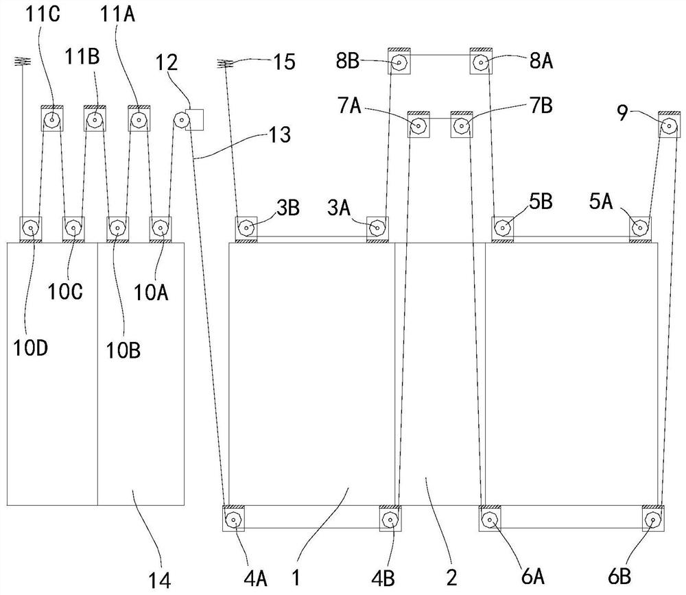
[0018] Example 1. A multi-winding composite pair of lifts, the elevator is a ladder, including a control system and a wellway, a car 1 and a heavy device in the wellway, and the car 1 connects to the heavy device through the traction system. The characteristics are as follows:

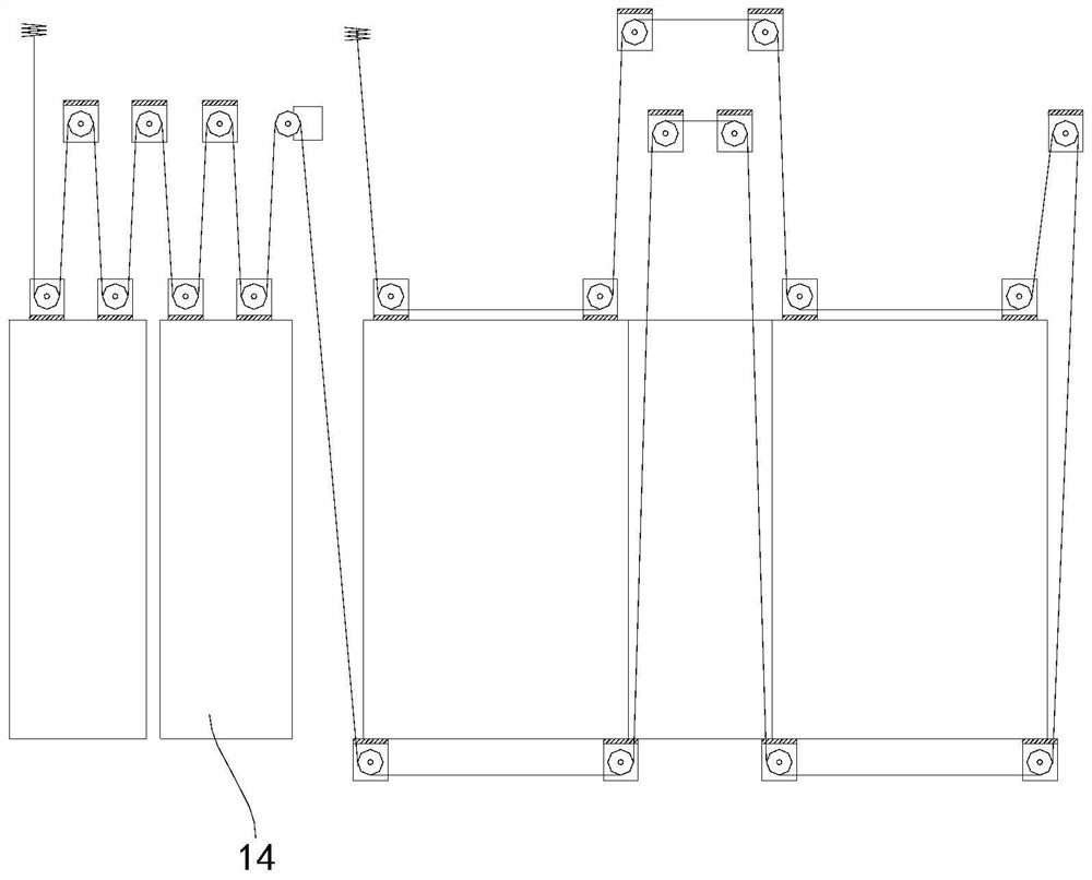
[0019] The central portion of the car 1 is provided with a passage 2, and two of the top of the car 1 are provided on the first movable pulley set 3a, 3b on the passage 2 side, and two at the bottom of the car 1 are provided in channel 2. On the top of the second moving pulleys 4a, 4b, the top of the car 1 is provided with a third moving pulley set 5a, 5b located on the other side of the channel 2, and two on the bottom of the car 1 are provided on the other side of the channel 2. The fourth movable pulleys 6a, 6b, and the channel 2 are provided with two first-stop pulley sets 7a, 7b close to the top of the wellway, and there are two second fixed pulley sets 8a, 8b, the car. One side is provided with a thi...

Embodiment 2

[0024] Example 2. Unlike Example 1, the counterweight device is a split structure, composed of two separate splittings, and the two split weights 14 are located on both sides of the car 1.

Embodiment 3

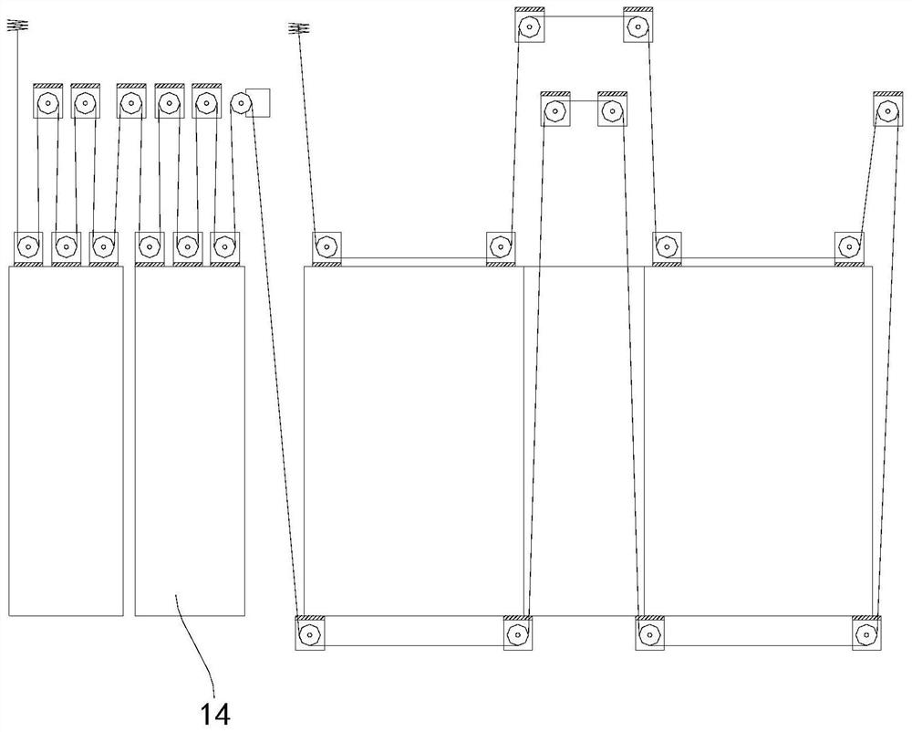
[0025] Example 3. Unlike Example 1, the counterweight device is a split structure, composed of two independent split values, and the number of the fifth moving pulley is six, eight, ten or twelve. A, the number of fourth sleeve is less than the number of fifth moving pulleys. Each split is equal to the number of fifth moving pulley packages on the weight 14. By changing the number of strokes of the fifth moving pulley, the more the number of the fifth moving pulley set 10 is, the larger the overall weight of the heavy device, the smaller the stroke of the heavy device.

[0026] In the elevators of Example 1 and Example 2, the traction of the heavy device was the same as the traction ratio of the car, which made the counter-repellent device and the car as the car. The weight of the room is close to the weight of the heavy device, and further reduces the cost of the elevator. In the elevator of Example 3, the traction ratio of the heavy device is larger than the traction ratio of th...


PUM


Abstract

The invention discloses a multi-winding composite traction elevator and an adjusting method. The elevator comprises a control system and a hoistway, wherein a lift car and a counterweight device are arranged in the hoistway; the lift car is connected with the counterweight device through a traction system; a channel is formed in the middle of the lift car; a first movable pulley block is arranged at the top of the lift car; two second movable pulley blocks are arranged at the bottom of the lift car; two third movable pulley blocks are arranged at the top of the lift car; two fourth movable pulley blocks are arranged at the bottom of the lift car; two first fixed pulley blocks are arranged above the channel; two second fixed pulley blocks are arranged above the first fixed pulley blocks; a third fixed pulley block is arranged above one side of the lift car; a fifth movable pulley block is arranged at the top of the counterweight device; a fourth fixed pulley block is arranged above the counterweight device; and the traction system comprises a traction machine arranged above the lift car. The multi-winding composite traction elevator provided by the invention has the advantages of being large in load capacity, high in safety and low in cost, or has the advantages of being large in load capacity, high in safety, convenient to install equipment in the hoistway and low in failure rate.

Description

Technical field [0001] The present invention belongs to the field of elevators, and in particular, the present invention relates to a multi-winding composite pair elevator and a adjustment method. Background [0002] The structure of the elevator includes a control system and a wellway, and there is a car and a heavy device in the wellway. The car is connected to the heavy device through the traction system, and the traction system includes a plurality of fixed pulley sets, a plurality of moving pulley sets and settings. The traction machine on the top of the wellway has a traction rope on the traction machine. One end of the traction rope is in turn around a plurality of fixed pulley sets and a plurality of moving pulley sets, wherein the pulley set and the wellway are fixed, a portion of the moving pulley set The car is connected, and the remaining pulley set is connected to the heavy device. When the traction machine works, the other end of the traction rope is wound or releas...

Claims


Application Information

Patent Timeline
Patent Type & Authority Applications(China)
IPC IPC(8): B66B11/00B66B11/08
CPCB66B11/008B66B11/0035
Inventor 荆华俊范江峰周建平王榆成
Owner WEIBO ELEVATOR
Learn More