Wall surface assembly type ceramic tile structure and installation method

A prefabricated and ceramic tile technology, which is applied in building construction, covering/lining, construction, etc., can solve problems such as difficult replacement of tiles, achieve fast and convenient installation, speed up installation efficiency, and reduce gaps

Inactive Publication Date: 2021-08-24
变形积木(北京)科技有限公司
View PDF1 Cites 3 Cited by
  • Summary
  • Abstract
  • Description
  • Claims
  • Application Information

AI Technical Summary

Problems solved by technology

The dry-hanging method has the advantages of firm installation and high construction efficiency, and there is no problem of hollowing and deformation, but it is difficult to replace tiles after damage, which needs to be improved

Method used


Image

  • Wall surface assembly type ceramic tile structure and installation method
  • Wall surface assembly type ceramic tile structure and installation method
  • Wall surface assembly type ceramic tile structure and installation method

Examples


Embodiment 1

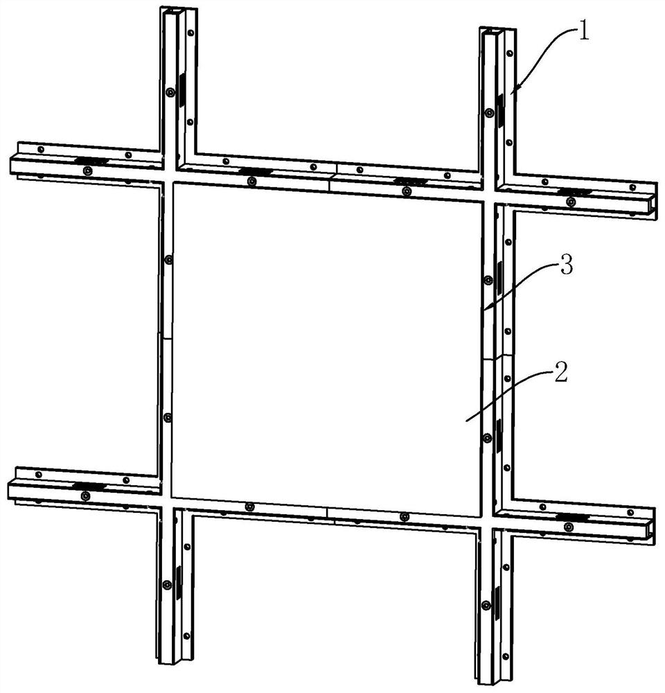
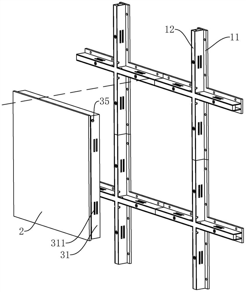
[0052] refer to figure 1 , figure 2 The wall prefabricated ceramic tile structure includes a keel assembly 1, a decorative tile 2, and a connecting assembly 3 for connecting the decorative tile 2 and the keel assembly 1. The keel assembly 1 is in the shape of a well, and the decorative tile 2 is square and installed on each keel assembly 1. In a well.

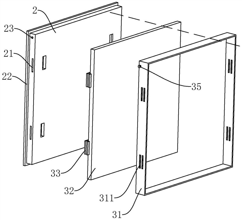
[0053] refer to figure 2 , image 3 , the connection assembly 3 includes a connection frame 31 , a backplane 32 , an insertion portion 33 and a driver 34 . The connecting frame 31 is square, and its inner side is attached to the outer edge of the decorative tile 2 , and the outer side is attached to the inner edge of the well of the keel assembly 1 . The backboard 32 is fixedly connected to the side of the decorative tile 2 facing the wall, and the connection method at this place can be fixed by screws, glued, etc. The backboard 32 is as large as the side of the decorative tile 2 facing the wall.

[0054] refer to imag...

Embodiment 2

[0068] refer to Figure 7 , Figure 8 , the only difference from the first embodiment is that the structure of the driving member 34 is different, and the connecting bolt 35 , the notch 1122 and the threaded hole 23 are not provided.

[0069] refer to Figure 8 , Figure 9 , the driving member 34 includes a driving gear 341, a driving rack 342, a connecting bar 343, a guide rod 344 and an operating handle. There are two driving racks 342 which are symmetrical to the center of the driving gear 341 , and the driving racks 342 mesh with the driving gear 341 . A rotating cavity 322 for the driving gear 341 is provided in the middle of the back plate 32 , and a square hole 3411 is formed in the middle of the driving gear 341 . The rotating cavity 322 communicates with a sliding cavity 323 for the driving rack 342 to snap into and slide. perpendicular to each other. A connection bar 343 is fixedly connected to two corresponding plug boards 332 . The sliding cavity 323 communi...


PUM


Abstract

The invention relates to a wall surface assembly type ceramic tile structure and an installation method, and relates to the field of ceramic tile installation. The wall surface assembly type ceramic tile structure comprises a keel assembly, a decorative ceramic tile and a connecting assembly used for connecting the decorative ceramic tile and the keel assembly, wherein the connecting assembly comprises a connecting frame, a back plate, an inserting part and a driving part; the connecting frame sleeves the outer side of the decorative ceramic tile and is clamped into the keel assembly; the back plate is connected to one side, facing a wall body, of the decorative ceramic tile; a guide groove for the inserting part to slide is formed in one side, facing the decorative ceramic tile, of the back plate; the driving part is used for driving the inserting part to slide outwards; the connecting frame is provided with a through hole for the inserting part to penetrate through; and the decorative ceramic tile is provided with a connecting hole for the inserting part to penetrate through. The ceramic tile structure is beneficial to rapid replacement of the damaged decorative ceramic tile, other intact decorative ceramic tiles cannot be influenced, and the replacement cost is low.

Description

technical field [0001] The present application relates to the field of tile installation, in particular to a wall-mounted tile structure and an installation method. Background technique [0002] Interior decoration includes multiple steps such as water and electricity renovation, wall decoration, and floor decoration. The main purpose of wall decoration is to protect the wall, improve the sound insulation and heat preservation capacity of the wall, and beautify the indoor environment. According to the different decorative materials, wall decoration is divided into paint, wallpaper, board and ceramic tile. For tile wall decoration, the assembly methods of tiles are divided into wet paste method and dry hanging method. [0003] The Chinese patent with the publication number CN111622449A discloses a dry-hanging system for an assembled ceramic tile wall, which includes: ceramic tiles, with installation grooves arranged at their four corners, and tiles arranged as a plurality of...

Claims


Application Information

Patent Timeline
IPC IPC(8): E04F13/08E04F13/22E04G21/14
CPCE04F13/08E04F13/081E04G21/14
Inventor 张轶然霍雨佳杨秀召
Owner 变形积木(北京)科技有限公司
Why Eureka
Try Eureka