Dielectric barrier fuel charge device

A charging device and medium barrier technology, applied in the charging system, combustion engine, internal combustion piston engine, etc., can solve the problems of weak connection, leakage, oil pipeline falling off, etc., to achieve good atomization and distribution uniformity, The effect of reducing pollution emissions and increasing flame temperature

Inactive Publication Date: 2021-08-24
合肥宝发动力技术股份有限公司
View PDF0 Cites 0 Cited by
  • Summary
  • Abstract
  • Description
  • Claims
  • Application Information

AI Technical Summary

Problems solved by technology

[0003] In order to reduce fuel consumption and appropriately reduce the emission of CO, HC, nitrogen oxides (NOx) and particulate matter (PM) synchronously, the prior art generally adopts the following two methods: 1. Add other types of fuel additives to the engine, which needs to be regularly The addition of additives increases the cost of users on a regular basis. In many cases, it does not have the effect of reducing both nitrogen oxides (NOx) and particulate matter (PM). It often only reduces one of the indicators, while the other indicators will rise instead. It is not a way to solve the problem at the root; 2. Adopt post-processing technology, that is, DPF+SCR technology. This double-drop technology has a strong purification effect, but the disadvantage is that the post-processing equipment needs to be cleaned regularly, and the cost of the pre- and post-processing is equal It is very tall and requires a lot of space, so it is very difficult to manufacture and install; in addition, in order to better ensure the combustion efficiency of fuel, before the fuel is injected into the engine, it is necessary to use a filter to filter the fuel gas. Harmful particles and water in the system are filtered out, while the common oil pipelines and filters on the market are usually plugged in, the connection is not firm, and it is easy to leak or even fall off. In addition, the filter The filter is usually installed directly on the chassis of the car, and the vibration during driving is more likely to cause the oil pipeline to fall off and the filter itself to be damaged. In view of this, we propose a dielectric barrier fuel charging device

Method used


Image

  • Dielectric barrier fuel charge device
  • Dielectric barrier fuel charge device
  • Dielectric barrier fuel charge device

Examples


Embodiment 1

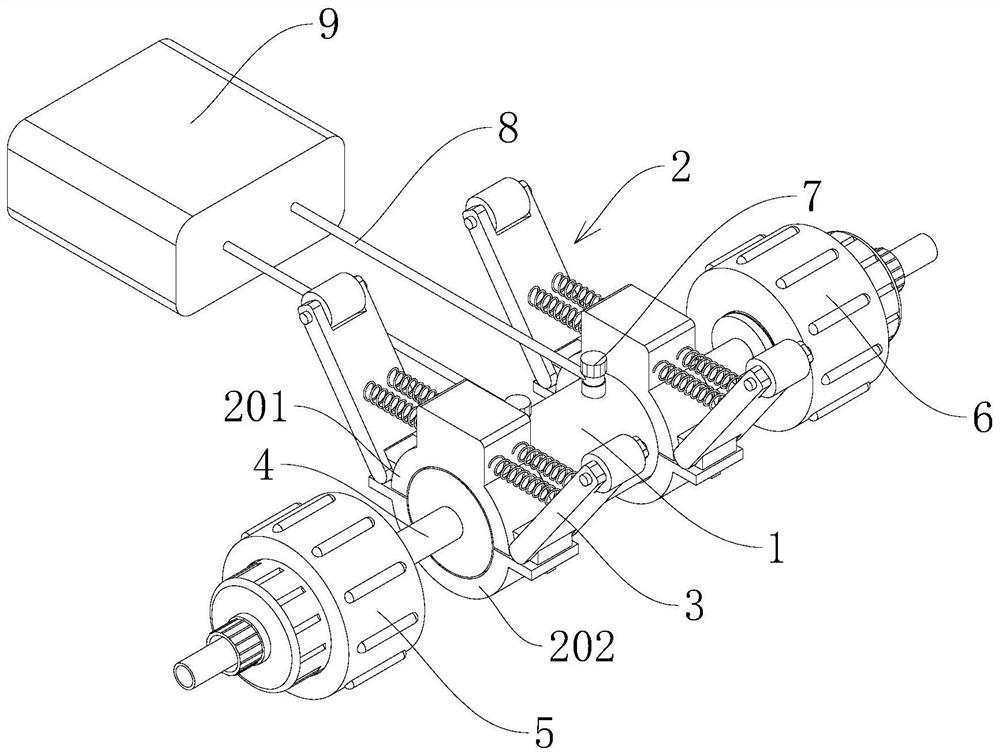
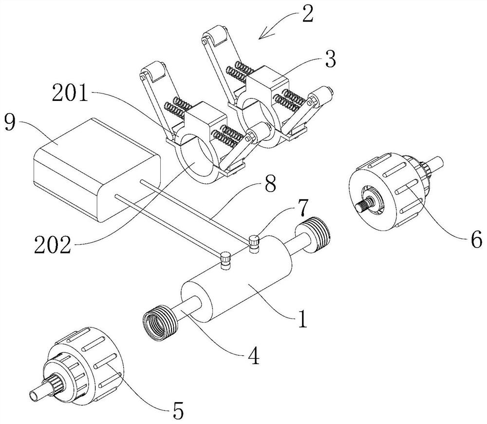
[0032] see Figure 1-3 , a dielectric barrier fuel charging device, including a fuel charging mechanism 1, the fuel charging mechanism 1 is connected with a shock absorbing device 2, the mounting shock absorbing device 2 includes a connecting mechanism, and the connecting mechanism includes an upper connecting half ring 201 and the lower connecting half-ring 202, the upper connecting half-ring 201 is connected with the shock absorbing mechanism 3, the lower connecting half-ring 202 is fixedly installed on the upper connecting half-ring 201 by fixing bolts; the two ends of the fuel charging mechanism 1 are connected with communicating pipes 4. The end of the connecting pipe 4 away from the fuel charging mechanism 1 is respectively connected with a first fuel filter device 5 and a second fuel filter device 6 .

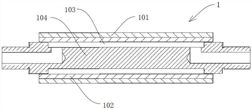
[0033] The fuel charging mechanism 1 is installed on the fuel inlet pipeline of the engine. The fuel charging mechanism 1 includes a high-voltage electric shaft 103, a m...

Embodiment 2

[0037] see Figure 4 , based on Example 1 but differing in that,

[0038] The damping mechanism 3 includes a support rod 301 and an auxiliary fixing block 303. One end of the support rod 301 is rotatably connected to the side end of the upper connecting half-ring 201, and one end of the supporting rod 301 away from the upper connecting half-ring 201 is rotatably connected to a roller 302. The roller 302 A limiting groove is arranged above, and the limiting groove is matched with the roller 302, and the limiting groove is installed on the installation surface close to the engine oil inlet pipeline; the auxiliary fixing block 303 is fixedly connected on the top surface of the upper connecting half ring 201, supporting A damping spring 304 is disposed between the rod 301 and the auxiliary fixing block 303 , and both ends of the damping spring 304 are fixedly connected to the side walls of the supporting rod 301 and the auxiliary fixing block 303 respectively.

[0039] The presen...

Embodiment 3

[0041] see Figure 5-6 , based on Examples 1-2 but differing in that,

[0042] Both the first fuel filter device 5 and the second fuel filter device 6 include a first connecting pipe 501 and a filter body 502, the first connecting pipe 501 is fixedly connected to the communicating pipe 4, and the first connecting pipe 501 is far away from the communicating pipe 4. One end is fixedly connected with the first connecting seat 503, the inner wall of the first connecting pipe 501 and the outer wall and the inner wall of the first connecting seat 503 are provided with thread layers, the filter body 502 is fixedly connected with the second connecting seat 504, the second The second connection seat 504 is fixedly connected with an extension tube 505, the front end of the extension tube 505 is fixedly connected with a first sealing ring 506, the second connection seat 504 and the outer wall of the extension tube 505 are provided with a connecting thread layer, and the extension tube 50...


PUM


Abstract

The invention discloses a dielectric barrier fuel charge device, and belongs to the technical field of fuel engine pretreatment devices. The dielectric barrier fuel charge device comprises a fuel charge mechanism, the fuel charge mechanism is connected with an installation damping device, the installation damping device comprises a connecting mechanism, the connecting mechanism comprises an upper connecting semi-ring and a lower connecting semi-ring, the upper connecting semi-ring is connected with a damping mechanism, and the lower connecting semi-ring is fixedly mounted on the upper connecting semi-ring through a fixing bolt; and the two ends of the fuel charge mechanism are connected with communicating pipes, and the ends, away from the fuel charge mechanism, of the communicating pipes are connected with a first fuel filtering device and a second fuel filtering device correspondingly. The problems that existing design is poor in purification effect, high in cost and large in operation difficulty, the connecting manner between a filter and an oil conveying pipeline is simpler, the sealing performance is poor, and leakage and falling off are prone to occurring are effectively solved.

Description

technical field [0001] The invention relates to the technical field of fuel engine pretreatment devices, in particular to a dielectric barrier fuel charging device. Background technique [0002] The formation of fuel mixture in diesel vehicles is carried out in the combustion chamber of the engine. Diesel is injected into the combustion chamber at high pressure, compressed and ignited, and then burned while spraying. This way of working determines that the mixture of diesel and air is not uniform, and there will inevitably be local oxygen deficiency or local oxygen enrichment. When oil is exposed to high temperature and lack of oxygen, it is easy to carbonize and form soot. The adjustment of diesel vehicle load is controlled by changing the fuel injection quantity. Under the current diesel technical conditions, the fuel-saving rate of diesel vehicles is limited. If more than 2% of the fuel-saving effect is to be obtained, additional technical means must be introduced to as...

Claims


Application Information

Patent Timeline
Patent Type & Authority Applications(China)
IPC IPC(8): F02M27/04F02M29/00F02M37/34F02M37/42
CPCF02M27/04F02M29/00F02M37/34F02M37/42Y02T10/12
Inventor 王远书莫志远李炜沈继成蒋旭东
Owner 合肥宝发动力技术股份有限公司
Why Eureka
Try Eureka