
Thrust bearing pack assembled in series

A technology of thrust bearing group and thrust bearing, which is applied in the direction of bearing assembly, rotating bearings, bearings, etc., can solve the problems that the thrust bearing cannot share the force, and the shared force is small, so as to save materials, reduce production costs, and guarantee The effect of uniformity

Active Publication Date: 2021-08-24
LUOYANG BEARING RES INST CO LTD
View PDF16 Cites 2 Cited by
  • Summary
  • Abstract
  • Description
  • Claims
  • Application Information

AI Technical Summary

Problems solved by technology

[0004] The purpose of the present invention is to provide a thrust bearing group assembled in series to solve the problem that the fourth and above thrust bearings cannot share the action force or share the action force too much after three or more thrust bearings are assembled in series in the prior art. minor technical issues

Method used


Image

  • Thrust bearing pack assembled in series
  • Thrust bearing pack assembled in series
  • Thrust bearing pack assembled in series

Examples


Embodiment 1

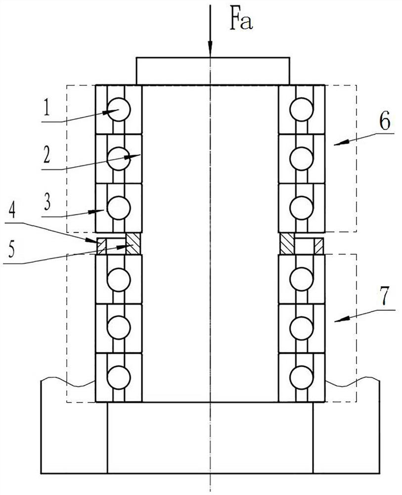
[0033] Such as figure 1 As shown, the thrust bearing group assembled in series includes thrust bearing 1 and spacer ring assembly. When the bearing group is subjected to axial force, it is ensured that the thrust bearings 1 are evenly stressed.

[0034] In this embodiment, thrust bearings 1 are connected in series with 3N groups, where N is an integer and greater than 1, and N in this embodiment is 2, that is, thrust bearings 1 are arranged in series with six groups, and the spacer assembly is arranged in the third group and Between the fourth thrust bearings 1, the thrust bearings 1 are divided into two sub-bearing groups, the two sub-bearing groups are respectively the upper bearing group 6 and the lower bearing group 7, wherein the thrust bearings 1 contained in the upper and lower bearing groups The numbers are triplets. In other embodiments, N may be 3. In this case, at least two spacer ring assemblies are required, so that the number of thrust bearings in each sub-bear...

Embodiment 2

[0045] The difference between this embodiment and Embodiment 1 is that in Embodiment 1, the bearing inner ring 2 of the thrust bearing 1 bears the external axial force, and the height of the outer spacer 4 is smaller than the height of the inner spacer 5 . In this embodiment, the bearing outer ring of the thrust bearing bears the external axial force, and the height of the outer spacer is greater than that of the inner spacer.

Embodiment 3

[0047] The difference between this embodiment and Embodiment 1 is that in Embodiment 1, the thrust bearings 1 are all thrust ball bearings. In this embodiment, the thrust bearings are all thrust roller bearings. In other embodiments, part of all thrust bearings may be thrust ball bearings, and the other part may be thrust roller bearings.


PUM


Abstract

The invention relates to a thrust bearing pack assembled in series. The thrust bearing pack assembled in series comprises at least four strings of thrust bearings arranged in series and space ring assemblies, wherein each space ring assembly is arranged between every two strings of adjacent thrust bearings so as to divide the thrust bearings into at least two sub-bearing packs, and the number of the thrust bearings of each sub-bearing pack is smaller than or equal to three; each space ring assembly comprises an outer space ring and an inner space ring, the outer space ring corresponds to a bearing outer ring of each thrust bearing, and the inner space ring corresponds to a bearing inner ring of each thrust bearing; when the bearing inner ring of each thrust bearing needs to bear external axial force, the height of each outer space ring is smaller than that of each inner space ring; and when the bearing outer ring of each thrust bearing needs to bear external axial force, the height of each outer space ring is larger than that of each inner space ring. By means of the design, all the thrust bearings participating in assembly bear the axial force together, so that the external axial force is distributed on all the thrust bearings, the stress uniformity of all the thrust bearings is improved, and the service life of the thrust bearings is effectively prolonged.

Description

technical field [0001] The invention relates to a thrust bearing set assembled in series. Background technique [0002] Bearing assembly can improve the rigidity and load carrying capacity of the entire shaft system. There are many ways of bearing assembly, among which series assembly is the most critical. The purpose of the series assembly method is to make the bearings participating in the assembly share the axial force at the same time, reduce the force on each bearing, and thus increase its life. [0003] At present, for the series combination of three or more thrust bearings, usually the first three thrust bearings receive the main force, and the fourth and above thrust bearings in series usually have no or less force, resulting in the fourth and above. Thrust bearings cannot share the force or share less force. Contents of the invention [0004] The purpose of the present invention is to provide a thrust bearing group assembled in series to solve the problem that t...

Claims


Application Information

Patent Timeline
Patent Type & Authority Applications(China)
IPC IPC(8): F16C19/10F16C19/54F16C35/06F16C41/02
CPCF16C19/10F16C19/54F16C35/061F16C41/02
Inventor 张振强张伟王东峰胡敬原赵洋
Owner LUOYANG BEARING RES INST CO LTD
Learn More