Direct-projection high-beam and low-beam car lamp lens
A technology of far and near light and lens, which is applied in the direction of headlights, motor vehicles, road vehicles, etc., can solve the problem that the lens does not have the cleaning function, and achieve the effect of easy replacement
- Summary
- Abstract
- Description
- Claims
- Application Information
AI Technical Summary
Problems solved by technology
Method used
Image
Examples
Embodiment 1
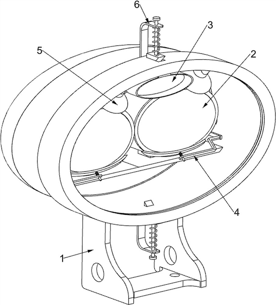
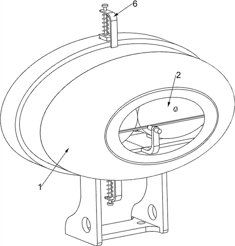
[0024] A direct projection far and near beam headlight lens, such as Figure 1-5 As shown, a first fixed frame 1, a fixed mechanism 2 and a turn signal lamp 3 are included, the first fixed frame 1 is provided with a fixed mechanism 2, and the inner wall of the first fixed frame 1 is fixed with a turn signal lamp 3 for lighting when the vehicle turns. .
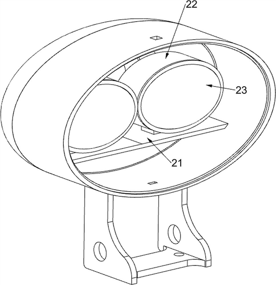
[0025] The fixing mechanism 2 includes a second fixing frame 21, a lamp frame 22, a lens 23 and an LED lamp 24. The second fixing frame 21 is fixedly installed in the first fixing frame 1, and two lamp frames 22 are fixedly installed on the second fixing frame 21. , The lamp frame 22 is provided with a lens 23, the lens 23 is used to irradiate the light to the road surface, and the LED lamp 24 is fixedly installed in the lamp frame 22.
[0026] This device is installed on the front of the car. When the vehicle is running normally at night and needs to use far and near lights, the led lamp 24 generates light, and the light shi...
Embodiment 2
[0028] On the basis of Example 1, such as Figure 6-7 As shown, a cleaning mechanism 4 is also included. The cleaning mechanism 4 is arranged on the second fixed frame 21. The cleaning mechanism 4 is used to wipe off the sticky dust on the surface of the lens 23. The cleaning mechanism 4 includes an electric push rod 41, a fixing bar 42, fixed plate 43, rotating shaft 44, gear 45, tooth bar 46, connecting bar 47, the third fixed frame 48, the first slide bar 49, sponge bar 411 and first return spring 412, fix on the second fixed frame 21 An electric push rod 41 is installed, and one end of the telescopic shaft of the electric push rod 41 is welded with a fixed strip 42, and two fixed plates 43 are fixedly installed on the inner wall of the first fixed frame 1, and the fixed plate 43 is rotatably connected with a rotating shaft 44. Affixed with gear 45, fixedly connected with two racks 46 on the fixed bar 42, fixedly connected with connecting bar 47 on the rotating shaft 44 awa...
Embodiment 3
[0031] On the basis of Example 2, such as Figure 5-6 As shown, a spraying mechanism 5 is also included, and the spraying mechanism 5 is located on the cleaning mechanism 4. The spraying mechanism 5 is used to spray the lens 23. The spraying mechanism 5 includes a fourth fixed mount 51, a pressure sensor 52, a rotating bar 53, Torsion spring 54 and sprayer 55, the fourth fixed frame 51 is fixedly installed on the fixed plate 43, is provided with pressure sensor 52 on the fourth fixed frame 51, is connected with rotating bar 53 on the tooth bar 46 that is far away from fixed bar 42, rotates A pair of torsion springs 54 are fixedly connected to the bar 53, and one end of the torsion spring 54 away from the rotating bar 53 is connected with the rack 46, and two sprayers 55 are arranged near the first fixed frame 1 inner wall of the turn signal lamp 3.
[0032] When the rack 46 moves towards the direction of the turn signal 3, the rotating bar 53 will press the pressure sensor 52,...
PUM
 Abstract
Description
Claims
Application Information
 - R&D
- Intellectual Property
- Life Sciences
- Materials
- Tech Scout
- Unparalleled Data Quality
- Higher Quality Content
- 60% Fewer Hallucinations
Browse by: Latest US Patents, China's latest patents, Technical Efficacy Thesaurus, Application Domain, Technology Topic, Popular Technical Reports.
© 2025 PatSnap. All rights reserved.Legal|Privacy policy|Modern Slavery Act Transparency Statement|Sitemap|About US| Contact US: help@patsnap.com


