
Motor bearing cover machining equipment

A technology for processing equipment and motor bearings, applied in metal processing equipment, turning equipment, turning equipment, etc., can solve the problems of poor machining dimension runout guarantee, out of tolerance, etc., and achieve the effect of improving machining efficiency

Pending Publication Date: 2021-08-27
宁波星源卓镁技术股份有限公司
View PDF6 Cites 0 Cited by
  • Summary
  • Abstract
  • Description
  • Claims
  • Application Information

AI Technical Summary

Problems solved by technology

[0003] In view of the related technologies mentioned above, the inventor believes that it is usually necessary to adopt the method of clamping twice on the CNC lathe for processing guarantee, but the position of the two clamping may change, resulting in poor runout guarantee and out-of-tolerance machining dimensions. Seriously, 40% of the products were scrapped due to runout out of tolerance

Method used


Image

  • Motor bearing cover machining equipment
  • Motor bearing cover machining equipment
  • Motor bearing cover machining equipment

Examples


Embodiment Construction

[0044] The following is attached Figure 1-7 The application is described in further detail.

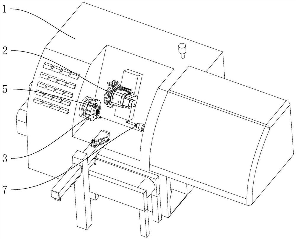
[0045] The embodiment of the present application discloses a motor bearing cover processing equipment. refer to figure 1 , The motor bearing cover processing equipment includes a lathe as a frame 1, a turning tool holder 2 arranged on one side of the frame 1, and an installation assembly installed on the lower side of the turning tool holder 2, and the installation assembly is used to fix the bearing cover. The installation assembly includes a positioning base 3 linked with the headstock in the frame 1, an outer circular pressing member 5 arranged on the positioning base 3, and an inner hole pressing member 7 oppositely arranged on the front side of the positioning base 3. A group of loading and unloading devices are also provided outside the frame 1 for automatically installing the bearing cover on the positioning base 3 .

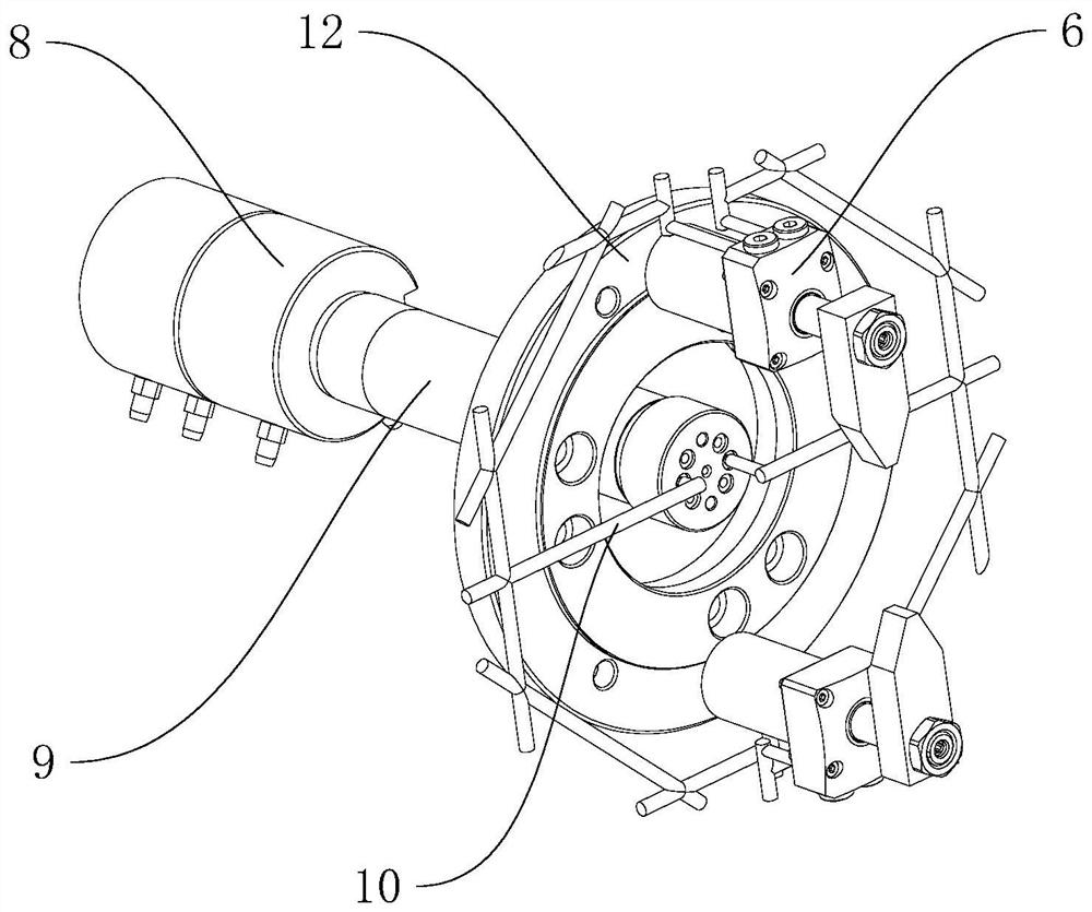
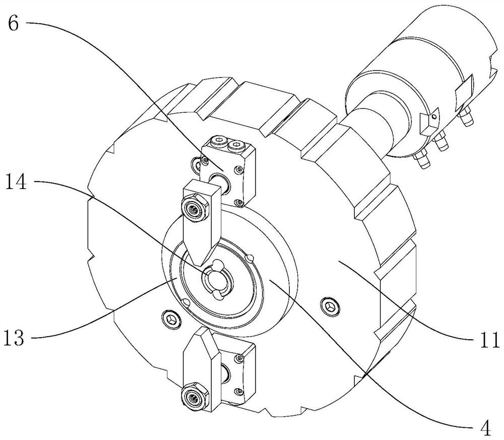
[0046] refer to figure 2 and image 3 The positioning ...


PUM


Abstract

The invention relates to motor bearing cover machining equipment which comprises a rack and a turning tool apron arranged on the rack. The rack is provided with a mounting assembly used for fixing a bearing cover, and the mounting assembly comprises a positioning base provided with a positioning boss inserted and positioned at one end of the bearing cover, an outer circle pressing component which comprises at least two rotary lifting oil cylinders which are distributed at the outer side of the positioning base and used for controlling the bearing cover to be pressed on the positioning base; and an inner hole pressing component which is arranged at the end, far away from the positioning base, of the rack and is used for pressing the bearing cover on the positioning base after being inserted into an inner hole. According to the motor bearing cover machining equipment, through joint cooperation of the rotary lifting oil cylinders and telescopic oil cylinders, the bearing cover can be fixed to the positioning base in two manners, and then the turning tool apron can machine an outer ring and the inner hole of the bearing cover in sequence without secondary disassembly and assembly.

Description

technical field [0001] The present application relates to the field of motor accessory processing equipment, in particular to a motor bearing cover processing equipment. Background technique [0002] At present, a kind of motor bearing cover produced has extremely high requirements for the outer circle and inner hole at both ends, and the full run-out position tolerance of the inner hole, outer circle, and seam is not greater than 0.05mm. For example, the bearing cover disclosed in the accompanying drawings needs to be processed Outer circle and inner hole. [0003] In view of the related technologies mentioned above, the inventor believes that it is usually necessary to adopt the method of clamping twice on the CNC lathe for processing guarantee, but the position of the two clamping may change, resulting in poor runout guarantee and out-of-tolerance machining dimensions. Seriously, 40% of the products were scrapped due to excessive runout. Contents of the invention [0...

Claims


Application Information

Patent Timeline
Patent Type & Authority Applications(China)
IPC IPC(8): B23B5/00B23B15/00B23Q7/00B23Q7/03B23Q7/04B25J15/08H02K15/00
CPCB23B5/00B23Q7/00B23Q7/043B23Q7/03B25J15/08H02K15/00
Inventor 谢胜川李占平朱徐俊
Owner 宁波星源卓镁技术股份有限公司
Learn More