Workbench capable of solving problems that plate cannot be automatically pushed and stability is poor during machining

A stable and workbench technology, applied in metal processing, metal processing equipment, metal processing machinery parts, etc., can solve problems such as potential safety hazards, easy finger injuries, and processing difficulties, so as to increase linkage, improve safety, and operate simple effect

Inactive Publication Date: 2021-08-27
周芳
View PDF6 Cites 0 Cited by
  • Summary
  • Abstract
  • Description
  • Claims
  • Application Information

AI Technical Summary

Problems solved by technology

[0002] The switchboard is generally composed of cabinets, switches, protection devices, monitoring devices, electric energy meters, and other secondary components. During the processing of cabinets, operations such as cutting and drilling are usually required on the workbench, so as to facilitate Forming and installation, but the existing workbench setup is relatively simple, and when processing, it is usually necessary to manually push the processing material for processing operations
Since the processing original is generally sharp, it is easy to accidentally injure fingers when manually pushing, and there is a certain safety hazard. At the same time, the existing workbench has poor stability during processing, which will increase the difficulty of processing.
[0003] Aiming at the deficiencies of the prior art, the present invention provides a workbench that cannot automatically push the board and has poor stability during processing. It has the advantages of automatic clamping and automatic material pushing, and solves the problem that the existing workbench is relatively simple to set It ensures that the material can be automatically pushed when the device is used for operation, which improves the safety during processing, and when processing, it automatically clamps and limits the position, improves the stability during processing, and makes the processing position more accurate. , increase the intelligence of the device when using

Method used


Image

  • Workbench capable of solving problems that plate cannot be automatically pushed and stability is poor during machining
  • Workbench capable of solving problems that plate cannot be automatically pushed and stability is poor during machining
  • Workbench capable of solving problems that plate cannot be automatically pushed and stability is poor during machining

Examples


Embodiment Construction

[0021] The technical solutions in the embodiments of the present invention will be clearly and completely described below with reference to the accompanying drawings in the embodiments of the present invention. Obviously, the described embodiments are only a part of the embodiments of the present invention, but not all of the embodiments. Based on the embodiments of the present invention, all other embodiments obtained by those of ordinary skill in the art without creative efforts shall fall within the protection scope of the present invention.

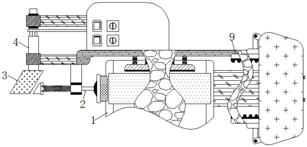
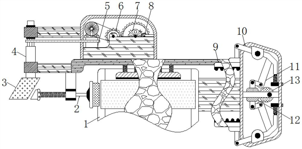
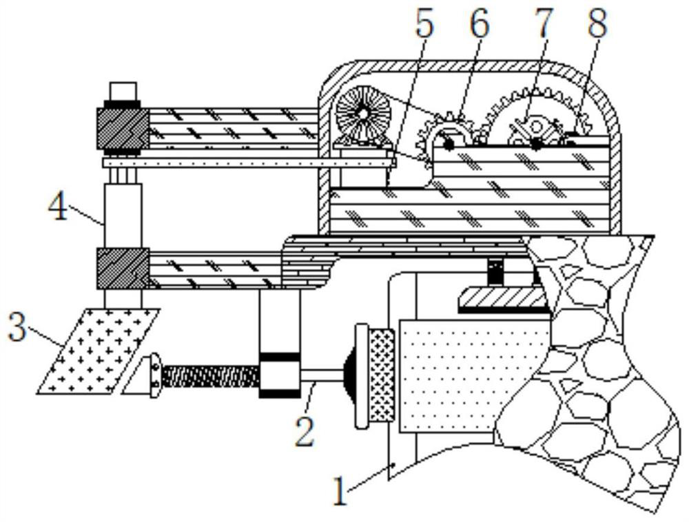
[0022] see Figure 1-3 , a workbench that can not automatically push the plate and has poor stability during processing, including a conveying plate 1, a baffle plate is arranged on the front of the conveying plate 1 to block the processing plate, and the conveying plate 1 is used to convey the raw materials. The left side of the plate 1 is movably connected with a push rod 2, and the transmitted processing plate is automatically push...


PUM


Abstract

The invention relates to the technical field of switchboards, and discloses a workbench capable of solving problems that a plate cannot be automatically pushed and stability is poor during machining, through cooperative use of a limiting plate, a first connecting rod, a second connecting rod, a movable plate and a cam, automatic clamping is conducted during original part manufacturing, stability of a machining plate during manufacturing is guaranteed, machining is more convenient.. Through cooperative use of a conveying plate, a push rod, a special-shaped roller, a first rotating shaft and a second rotating shaft, when the workbench is used for machining and manufacturing, materials are automatically pushed, manual pushing is not needed, a situation that the manual pushing is needed during raw material machining is avoided, more time and labor are saved, meanwhile, fingers are prevented from being accidentally injured during manual plate pushing, safety during original part machining is improved. And through cooperative use of the second rotating shaft, a pinion, a special-shaped disc and a rotating disc, the two steps of automatic limiting and automatic plate pushing are linked during the original part machining, so that linkage performance of the whole device is improved, and operation is simpler.

Description

technical field [0001] The invention relates to the technical field of switchboards, in particular to a workbench which solves the problem of inability to push a plate automatically and poor stability during processing. Background technique [0002] The switchboard is generally composed of cabinets, switches, protection devices, monitoring devices, electric energy meters, and other secondary components. During the processing of the cabinets, it is usually necessary to perform operations such as cutting and drilling on the workbench, so as to facilitate Forming and installation, but the existing table setting is relatively simple, wherein when processing, it is usually necessary to manually push the processing material to carry out the processing operation. Since the processing original is generally sharp, it is easy to accidentally injure the fingers when manually pushing, and there is a certain safety hazard. At the same time, when the existing workbench is processed, the s...

Claims


Application Information

Patent Timeline
IPC IPC(8): B23Q3/06B23Q7/06
CPCB23Q3/062B23Q7/06
Inventor 周芳
Owner 周芳
Why Eureka
Try Eureka