Full-automatic street lamp plate cutting and grinding device

A cutting and grinding, fully automatic technology, which is applied in the direction of grinding/polishing safety devices, grinding machines, grinding racks, etc., can solve problems such as poor performance, grinding wheel wear, and easy displacement, so as to improve the grinding effect and improve the Service life, effect of avoiding displacement

Inactive Publication Date: 2021-08-27
吴远鸳
View PDF0 Cites 1 Cited by
  • Summary
  • Abstract
  • Description
  • Claims
  • Application Information

AI Technical Summary

Problems solved by technology

[0003] Street lamps need to use plates in assembly. The plates need to be cut and polished before use. At present, many devices for cutting and grinding the plates do not fix the plates very well, which makes the plates prone to displacement during the grinding process. After the plate is polished, it has a great impact on the subsequent work. The existing device does not add cooling effect to the grinding wheel, which will make the grinding wheel wear more seriously, and the grinding effect on the plate is not good, and also increases the processing cost.

Method used


Image

  • Full-automatic street lamp plate cutting and grinding device
  • Full-automatic street lamp plate cutting and grinding device
  • Full-automatic street lamp plate cutting and grinding device

Examples


Embodiment 1

[0028] see Figure 1-5 :

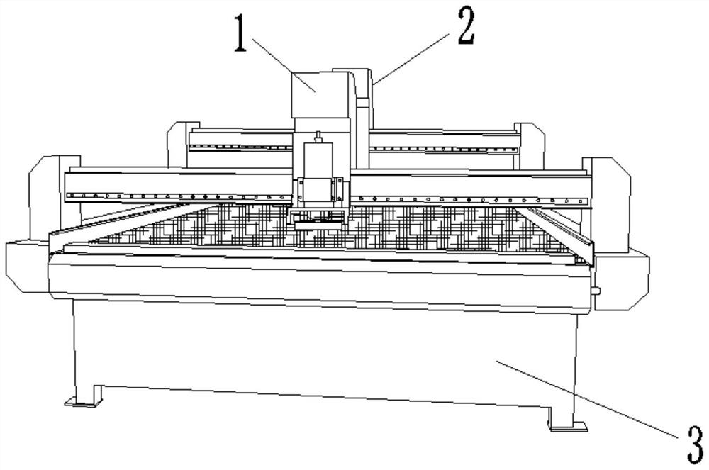
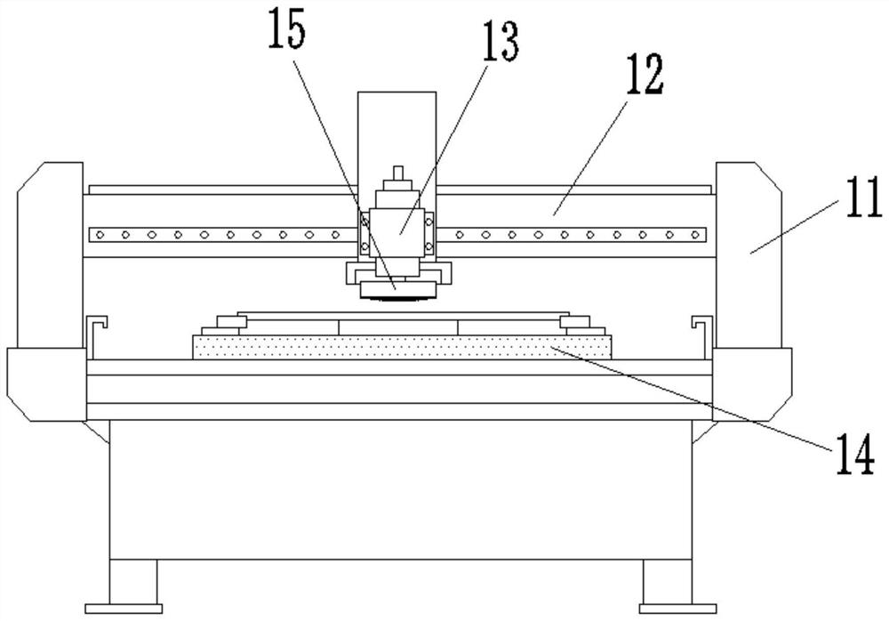
[0029] The present invention provides a technical solution: a fully automatic cutting and grinding device for street lamp panels, including a grinding mechanism 1, a cutting mechanism 2 and a support base 3, the grinding mechanism 1 is installed on the top of the support base 3, and the cutting mechanism 2 is arranged on the back of the grinding mechanism 1 , the grinding mechanism 1 includes a support frame 11, a support cross bar 12, a main shaft 13, a workbench 14 and a grinding wheel 15, the support cross bar 12 is arranged above the support base 3, the support frame 11 is installed on the left and right sides of the support cross bar 12, and the main shaft 13 is arranged at the center of the support cross bar 12, the workbench 14 is installed at the top of the support base 3, and the grinding wheel 15 is arranged at the bottom of the main shaft 13.

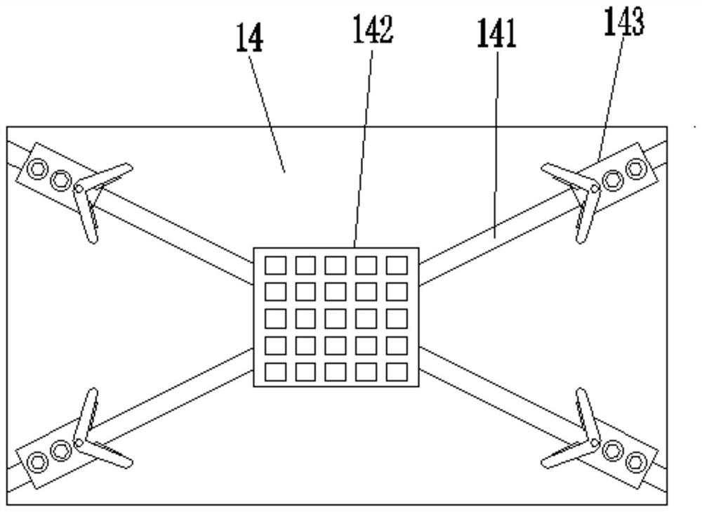
[0030] The workbench 14 includes a T-shaped slot 141, an electromagnetic chuck 142 and a positi...

Embodiment 2

[0033] see Figure 6-8 :

[0034] Grinding wheel 15 comprises running wheel 151, grinding plate 152, push rod 153, back-moving spring 154, rubber cover 155 and cooling mechanism 156, and running wheel 151 is arranged on grinding wheel 15 inside, and running wheel 151 two ends are all provided with chute, and grinding The plate 152 is arranged below the runner 151, the ejector rod 153 is installed on both ends of the grinding plate 152 and extends inside the chute, the top of the return spring 154 is fixedly connected to the top of the inner wall of the chute and the bottom is fixedly connected to the top of the ejector rod 153, and the rubber sleeve 155 The top is fixedly connected with the bottom of the runner 151 and the bottom is fixedly connected with the top of the grinding plate 152. The ejector rod 153 moves upward in the inner chute of the runner 151, and then bounces back through the return spring 154 provided inside to make the grinding wheel 15 The pressing effect ...


PUM


Abstract

The invention discloses a full-automatic street lamp plate cutting and grinding device which comprises a grinding mechanism, a cutting mechanism and a supporting base. The grinding mechanism is installed at the top of the supporting base, and the cutting mechanism is arranged on the back face of the grinding mechanism. The grinding mechanism comprises supporting frames, a supporting cross rod, a main shaft, a workbench and a grinding wheel, the supporting cross rod is arranged above the supporting base, and the supporting frames are installed on the left side and the right side of the supporting cross rod. According to the full-automatic street lamp plate cutting and grinding device, by the arrangement of a cooling mechanism, a fixing seat drives a bag to move upwards through pressing of a grinding plate, arc-shaped pressing plates contract inwards to press a pressing plate downwards, then the generated extrusion force is larger through upward moving of the bag, cooling liquid in the bag is extruded into a cooling groove from a leakage groove through the generated extrusion force by air in the bag, and then the grinding plate is cooled. The service life of the grinding wheel is prolonged, and the cost is saved.

Description

technical field [0001] The invention relates to the technical field of street lamp plate cutting and grinding, in particular to a fully automatic cutting and grinding device for street lamp plates. Background technique [0002] Every night, in modern cities, you can see all kinds of dazzling street lamps. Street lamps are not only used as decorations to add a touch of splendor to the night of the city, but also provide convenience for pedestrians and vehicles at night, avoiding the Many traffic accidents caused by insufficient luminosity. [0003] Street lamps need to use plates in assembly. The plates need to be cut and polished before use. At present, many devices for cutting and grinding the plates do not fix the plates very well, which makes the plates prone to displacement during the grinding process. After the plate is polished, it has a great impact on the subsequent work. The existing device does not add cooling effect to the grinding wheel, which will make the grin...

Claims


Application Information

Patent Timeline
Patent Type & Authority Applications(China)
IPC IPC(8): B24B7/10B24B55/02B24B27/02B24B41/00B24B41/06B24B41/02B24B27/00B23P23/04
CPCB23P23/04B24B7/10B24B27/0046B24B27/02B24B41/007B24B41/02B24B41/068B24B55/02
Inventor 吴远鸳
Owner 吴远鸳
Why Eureka
Try Eureka