Power switch cabinet manufacturing and processing system

A technology for processing systems and switch cabinets, which is applied to manufacturing tools, metal processing equipment, grinding workpiece supports, etc., can solve problems such as affecting work efficiency, increasing workload, and damage to power switch cabinets, and achieves enhanced processing effects. Grinding effect, ensuring stable effect

Inactive Publication Date: 2021-08-27
叶欢欢
View PDF0 Cites 1 Cited by
  • Summary
  • Abstract
  • Description
  • Claims
  • Application Information

AI Technical Summary

Problems solved by technology

[0003] However, the following problems exist in the production and processing of power switch cabinets at present: 1. Before the traditional power switch cabinets are processed, they are mostly placed on the workbench and not fixed. Therefore, during the processing, the power switch cabinets are easy to Offset, lack of stability, and easy to cause damage to the power switch cabinet, and then cause the power switch cabinet to be defective;
[0004] 2. During the processing of general power switch cabinets, most of the workers spray cleaning fluid on the surface of the power switch cabinets. Because the cleaning fluid contains chemical components, it is easy to cause harm to workers, and after polishing the surroundings of the power switch cabinets, The top needs to be polished twice, which increases unnecessary workload and affects work efficiency

Method used


Image

  • Power switch cabinet manufacturing and processing system
  • Power switch cabinet manufacturing and processing system
  • Power switch cabinet manufacturing and processing system

Examples


Embodiment Construction

[0035]The embodiments of the present invention will be described in detail below with reference to the accompanying drawings, but the present invention can be implemented in many different ways defined and covered by the claims.

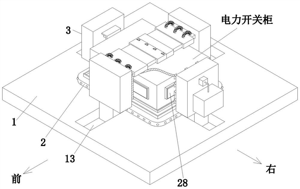
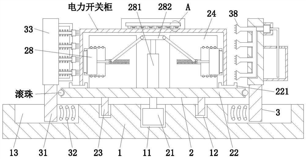
[0036] Such as Figure 1 to Figure 9 The manufacturing and processing system of a power switchgear shown includes a base 1, a support unit 2 and an execution unit 3. A fixing groove 11 is provided at the center of the upper end of the base 1, and an annular slide is provided at the upper end of the base 1 with the fixing groove 11 as the center of a circle. slot 12, and the upper end of the base 1 is provided with a limit chute 13 along its surroundings, the limit chute 13 is perpendicular to the edge of the base 1, the upper end of the base 1 is equipped with a support unit 2, and the execution unit 3 is slidably installed on the limit slide Inside slot 13, where:

[0037] The support unit 2 includes a transmission motor 21, a supporting plate 22, ...


PUM


Abstract

The invention provides a power switch cabinet manufacturing and processing system. The system comprises a base, a supporting unit and execution units, the upper end of the base is provided with limiting sliding grooves along the periphery of the base, the supporting unit is mounted at the upper end of the base, and the execution units are slidably mounted in the limiting sliding grooves. The power switch cabinet manufacturing and processing system can solve the following problems that most traditional power switch cabinets are placed on a workbench and are not fixed before being processed, consequently, in the processing process, the power switch cabinets are prone to deviating and lack of stability, gouges of the power switch cabinets are prone to being caused, and then badness of the power switch cabinets is caused; and when common power switch cabinets are processed, cleaning liquid is sprayed on the surfaces of most power switch cabinets by workers, due to the fact that the cleaning liquid contains chemical components, the workers are prone to being injured, after the peripheries of the power switch cabinets are ground, secondary grinding treatment needs to be performed on the tops, consequently, unnecessary workloads are increased, and the working efficiency is influenced.

Description

technical field [0001] The invention relates to the technical field of electric switch cabinets, in particular to a manufacturing and processing system for electric switch cabinets. Background technique [0002] The power switch cabinet is a kind of electrical equipment. The outside line of the power switch cabinet first enters the main control switch in the cabinet, and then enters the sub-control switch. Each branch is set according to its needs. The main function of the power switch cabinet is to generate power, transmit power, In the process of power distribution and power conversion, switch, control and protect electrical equipment. The components in the power switch cabinet are mainly composed of circuit breakers, isolating switches, load switches, operating mechanisms, transformers and various protection devices; Power switchgear is mainly used in various occasions such as power plants, substations, petrochemicals, residential quarters, and high-rise buildings; during...

Claims


Application Information

Patent Timeline
Patent Type & Authority Applications(China)
IPC IPC(8): B24B27/00B24B7/10B24B41/06B24B47/22B24B55/06B08B3/02
CPCB08B3/02B24B7/10B24B27/0076B24B41/06B24B47/22B24B55/06
Inventor 叶欢欢
Owner 叶欢欢
Why Eureka
Try Eureka