

Laboratory waste liquid treatment equipment
A waste liquid treatment, laboratory technology, applied in the direction of neutralization water/sewage treatment, etc., can solve the problem of inability to guarantee the safety of waste liquid treatment
- Summary
- Abstract
- Description
- Claims
- Application Information
AI Technical Summary
Problems solved by technology
Method used
Image

Examples
Embodiment 1
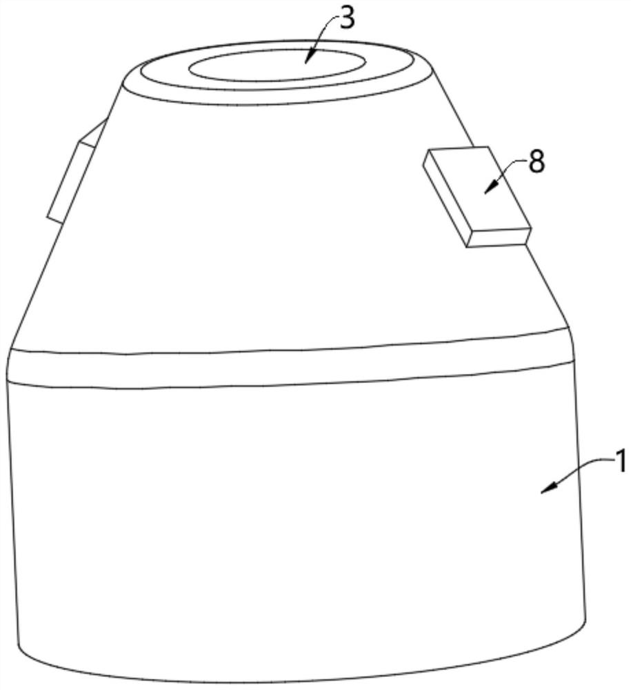
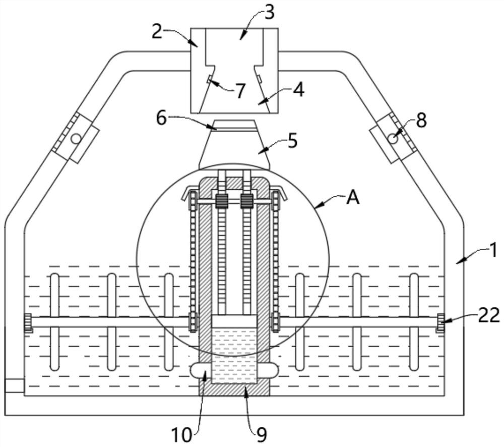
[0037] see Figure 1-Figure 4 , a kind of waste liquid treatment equipment used in the laboratory, comprising a housing 1, a liquid injection cylinder 2 is fixedly installed on the inner top wall of the housing 1, and a liquid injection tank 3 is opened in the upper half of the liquid injection cylinder 2, and the injection The lower half of the inside of the liquid cylinder 2 is provided with a limited flow groove 4;
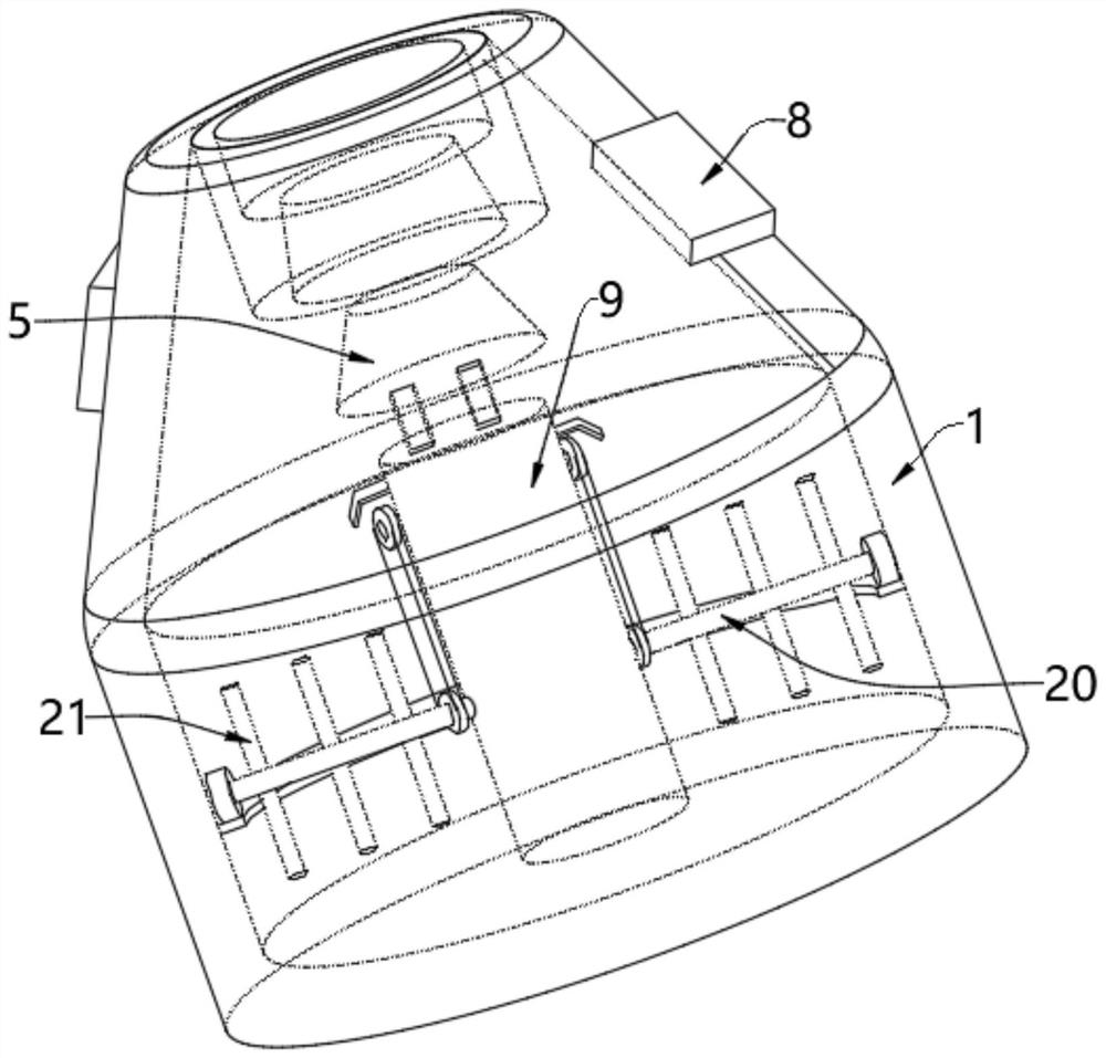
[0038]The inner bottom wall of the housing 1 is rotatably provided with an inner cylinder 9, and a flow-limiting plug 5 coupled with the shape of the inner wall of the flow-limiting groove 4 is movably arranged above the inner cylinder 9. The plug 5 is a conical body coupled with the shape of the inner wall of the flow-limiting groove 4. The flow-limiting plug 5 of the conical truncated body can completely block the flow-limiting groove 4. The control device arranged inside the inner cylinder 9 drives the flow-limiting plug 5 to Move up and down in the flow li...
Embodiment 2
[0044] see Figure 1-Figure 3 , on the basis of Embodiment 1, the outer wall of the current limiting plug 5 is provided with a copper coil 6, the inner wall of the current limiting tank 4 is provided with a voltage plate 7 matching the copper coil 6, and the two sides of the housing 1 are also provided with heat dissipation 8, the output end of the voltage sheet 7 is electrically connected to the input end of the radiator 8. When the current limiting plug 5 moves upward and completely extends into the current limiting groove 4, it proves that the temperature in the housing 1 is relatively high at this time, and the current limiting plug 5. The copper coil 6 on the current-limiting plug 5 fully inserted into the current-limiting groove 4 is in contact with the voltage plate 7 on the inner wall of the current-limiting groove 4, and conducts the circuit of the radiator 8, which can make the radiator 8 work and dissipate heat, effectively The excess heat in the casing 1 is dissipa...
Embodiment 3
[0046] see Figure 2-Figure 5 , on the basis of Embodiment 1 and Embodiment 2, the outer walls of the two connecting rods 13 are also provided with teeth 14, the outer walls of the teeth 14 are meshed with a driving wheel 15, and the center of the driving wheel 15 is fixedly installed with a transverse shaft 16 , the two ends of the transverse shaft 16 extend to the outside of the inner tube 9 and are fixedly connected with driving wheels 17, the outer walls of the two driving wheels 17 are movably provided with transmission chains 18, and the inner walls of the two transmission chains 18 are movably provided with The driving wheel 19 and the centers of the two driven wheels 19 are fixedly equipped with stirring shafts 20, and the two stirring shafts 20 are respectively rotated and arranged on the left and right sides of the inner cylinder 9, and the outer walls of the two stirring shafts 20 are fixedly equipped with stirring blades 21 , the ends of the two stirring shafts 20 ...
PUM
 Abstract
Description
Claims
Application Information