
Injection molding part material root breaking equipment

A technology of injection molded parts and material roots, which is applied in metal processing and other directions, can solve problems such as low production efficiency, difficult debugging, expensive tools, etc., and achieve the effects of reducing equipment costs, manpower and equipment costs, and production costs

Active Publication Date: 2021-08-31
上海磐云科技有限公司
View PDF7 Cites 0 Cited by
  • Summary
  • Abstract
  • Description
  • Claims
  • Application Information

AI Technical Summary

Problems solved by technology

[0003] At present, the number of keys on computer keyboards is huge, and the keys are made by injection molding. During injection molding, multiple keys are connected by material roots, and most of the material roots are removed by traditional techniques such as punching and high-speed milling machines. The price is high and the consumables are expensive.
There are 64 holes in the injection mold of the button, and 64 buttons are formed at one time. In the process of removing the root, 64 knives need to be debugged, which is difficult to debug and the tools are expensive, and the production efficiency is low.

Method used


Image

  • Injection molding part material root breaking equipment
  • Injection molding part material root breaking equipment
  • Injection molding part material root breaking equipment

Examples


Embodiment Construction

[0043] The present invention will be further described in detail below in conjunction with the accompanying drawings and embodiments. It should be understood that the specific embodiments described here are only used to explain the present invention, but not to limit the present invention. In addition, it should be noted that, for the convenience of description, only some structures related to the present invention are shown in the drawings but not all structures.

[0044]In the description of the present invention, unless otherwise clearly specified and limited, the terms "connected", "connected" and "fixed" should be understood in a broad sense, for example, it can be a fixed connection, a detachable connection, or an integrated ; It can be a mechanical connection or an electrical connection; it can be a direct connection or an indirect connection through an intermediary, and it can be the internal communication of two components or the interaction relationship between two c...


PUM


Abstract

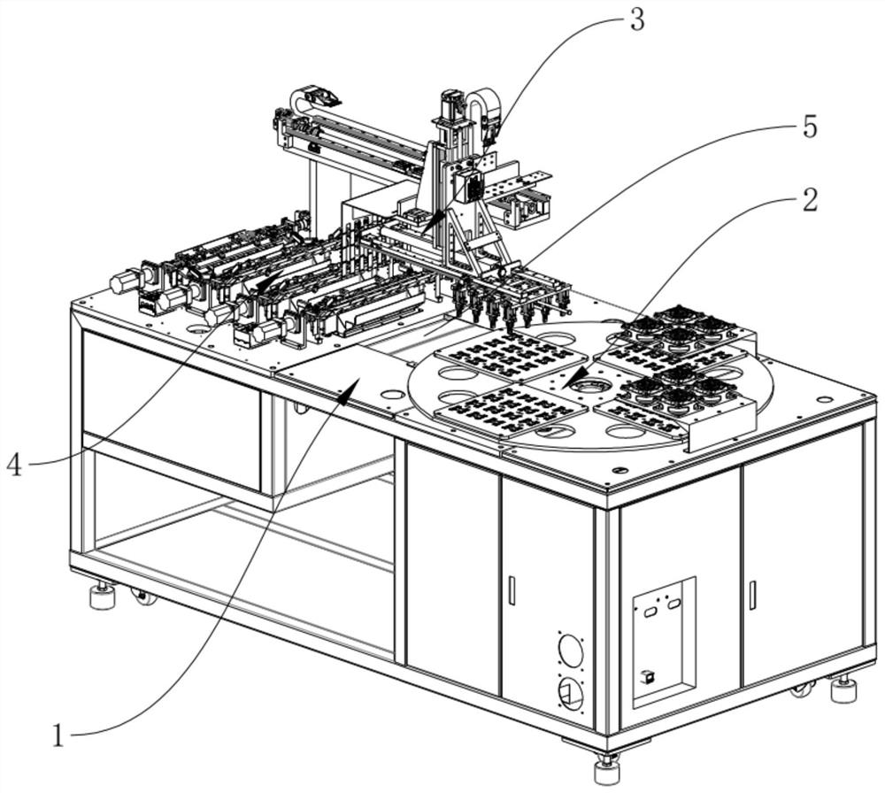
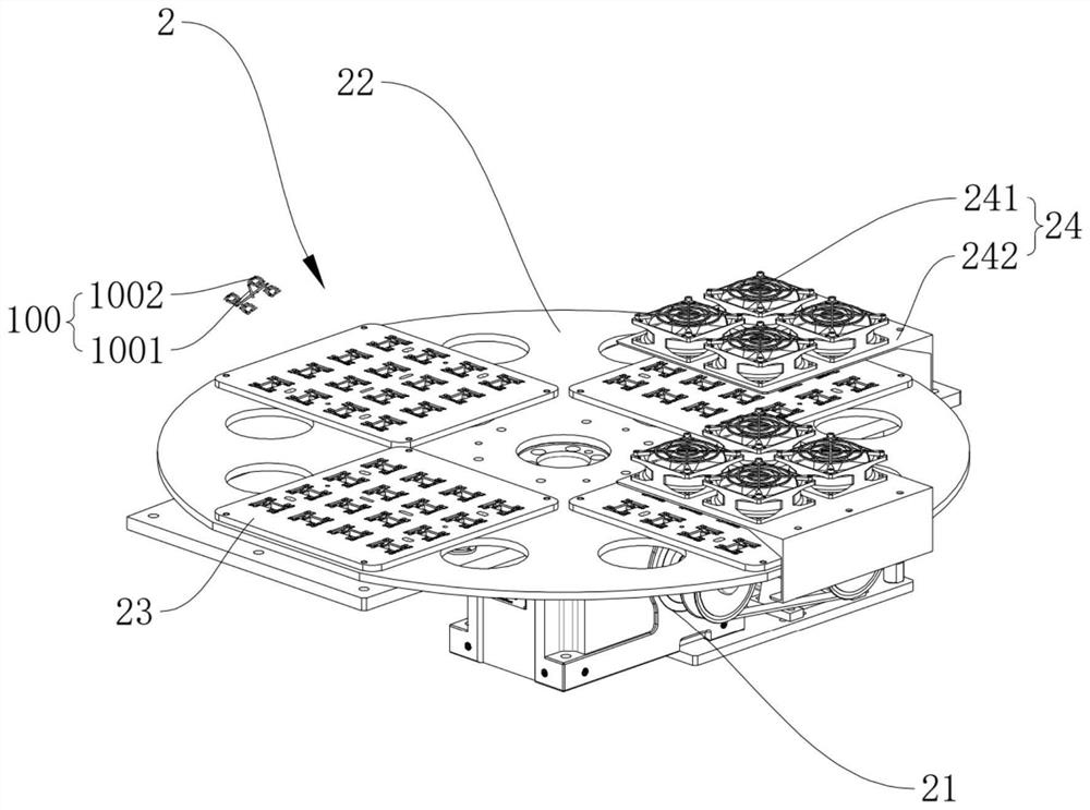
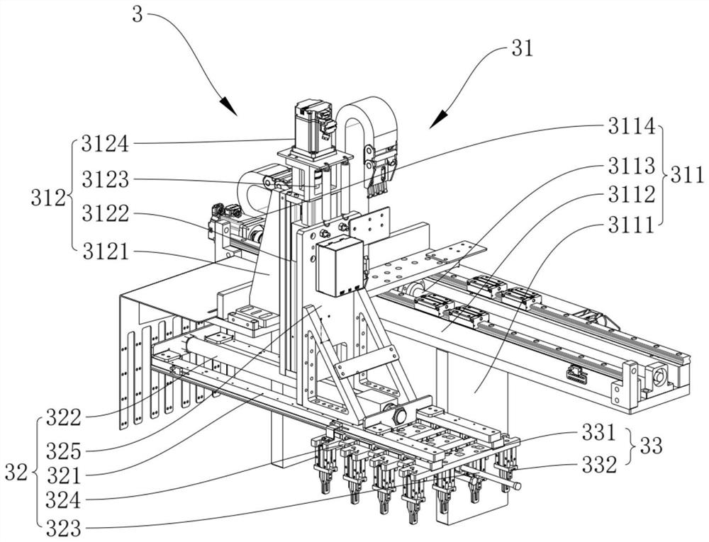
The invention relates to the technical field of injection molding part machining, and discloses injection molding part material root breaking equipment. The injection molding part material root breaking equipment is used for breaking a material root of an injection molding part and comprises a workbench, wherein a cooling feeding device, a material conveying device and a breaking device are arranged on the workbench, and the cooling feeding device is configured to bear the injection molding part subjected to injection molding and can also cool the injection molding part; the material conveying device is configured to grab the cooled material roots and convey the injection molding parts to the breaking device; the breaking device comprises two breaking assemblies which are symmetrically arranged at intervals, the two breaking assemblies are configured to clamp products on the two sides of the material roots correspondingly, and the breaking assemblies can drive the products to rotate relative to the material roots, so that the products can be separated from the material roots. According to the injection molding part material root breaking equipment, automatic separation of products and material roots of injection molding parts and integrated arrangement of cooling and breaking of the injection molding parts are achieved, so that the equipment cost is reduced, the production efficiency is improved, the material roots of the cooled injection molding parts are convenient to remove, and the material root removing quality is improved.

Description

technical field [0001] The invention relates to the technical field of injection molded parts processing, in particular to a material root breaking device for injection molded parts. Background technique [0002] The popularization of computers and the formation and development of computer culture have brought revolutionary changes to the development of human society. The rapid development of network technology has made the Internet penetrate into all aspects of people's work, study and life. The application of information technology has made human knowledge It can be rapidly disseminated, accumulated, analyzed, combined, stored and reproduced, thus giving people more means to use, acquire and redevelop knowledge, so the growth rate of knowledge is particularly rapid in the information age. Computers and information networks have integrated into today's social life and become an inseparable part of human life. As the production and development of the physical components of ...

Claims


Application Information

Patent Timeline
IPC IPC(8): B26F3/00B26D7/08B26D7/18B26D7/06B26D7/02B29C45/72
CPCB26F3/00B26D7/08B26D7/1845B26D7/06B26D7/02B29C45/7207Y02W30/62
Inventor 黄大炜王伟张国春
Owner 上海磐云科技有限公司
Learn More